Spooky Swap
Part 1 of 3: Haunted House Pinball
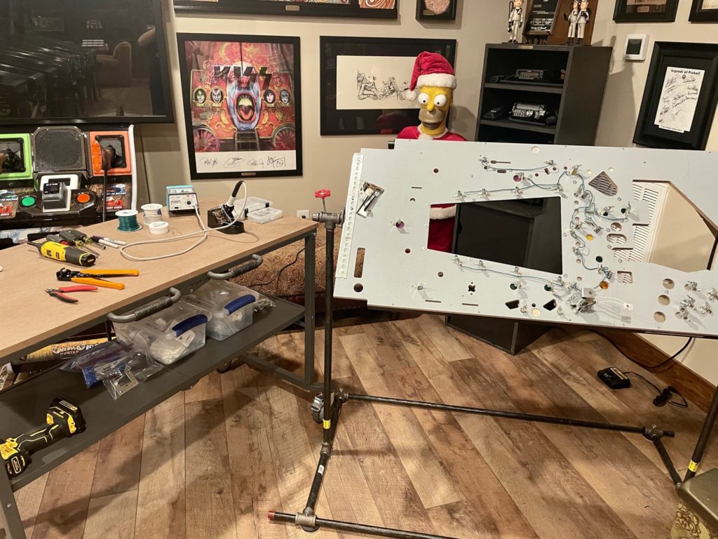
It’s October as I begin to write this. No, I’m not rushing to finish up my Gottlieb Haunted House playfield swaps because it’s October (Halloween), it’s just time that I get to work on it. I also know that there is no way I’ll get the game done by Halloween but read on to see how it all ends!
More than a year ago my buddy Keith Burns called to let me know that a friend of his had a pinball machine they wanted to sell. By the description it sounded like a Gottlieb Haunted House. I called the number he gave me and talked with the gentleman about the machine but the price was just not quite right for the condition it was in. I had always wanted a Gottlieb Haunted House but it needed to be in pristine condition or “cheap” so I could restore it. He sent pics and could see obvious amounts of wear on the playfield – pretty common on this title. I decided to pass on the purchase.
A year later and I heard back from Keith that his friend was still looking to sell – and this time at a lower price. His buddy shared the new price with me via text, and I bought it on the spot with a three word reply “I’ll take it”. I was assuming that it was a mostly working machine (it was) My plan was to order 3 new playfields from Mirco in Germany. Then get a new set plastics, new Pops and any new posts/hardware needed to make it look/function great.
I drove to Nashville to pick it up and arrived in the early afternoon in May of 2021. I took my wife’s new Jeep on it’s virgin pin hauling trip. When I arrived, I was surprised to see another pinball game in his house. It sounded like he was a relatively new pinball person and was probably only casually involved in the hobby. I was correct on both accounts, but still he had another game. The other game was a pimped out Munsters. I stared at it for a bit trying to discover what trim level the game was. After a minute of looking it over, I told the owner it looked like a Munsters refinery edition. He said he bought it from a neighbor and that the owner told him it was a game that a company had “put a lot of extras” into. When I bent down to open the coin door the sticker on the cabinet gave it away – it WAS a Refinery Edition. In fact, I told the owner there was likely a picture of this exact same game on the internet. We went the the Refinery site and sure enough – his game was right there. Too cool
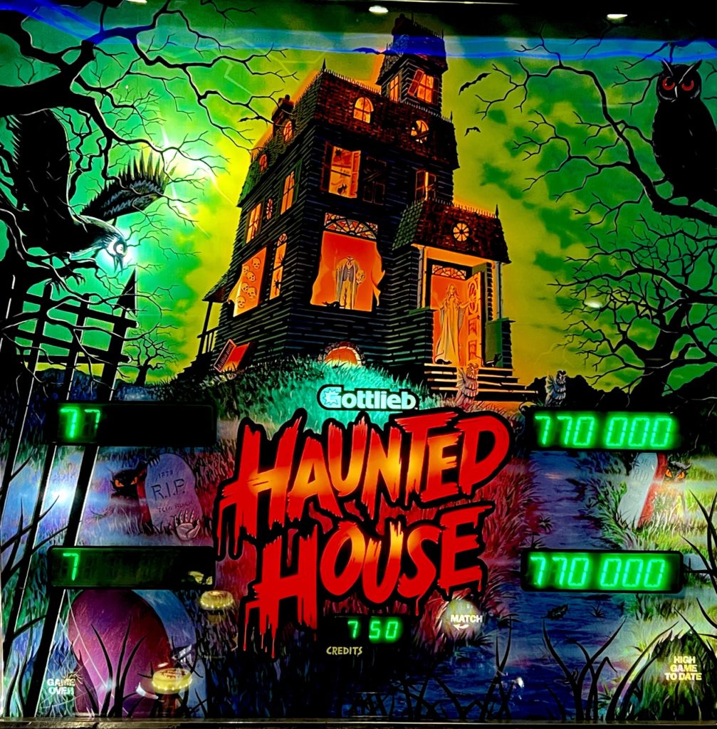
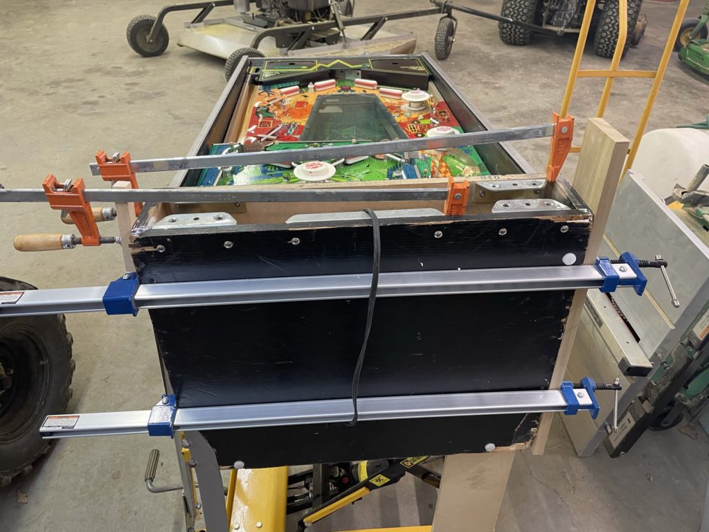
I played Munsters for a bit (enjoyed it thoroughly) and noticed a machine gunning sling shot. I asked if he would mind if I gapped that switch to fix the problem and he was happy to have me do so. Once the sling was corrected, I started over to check out the Haunted House. The cabinet was in fair condition, all the damage was in the rear. It could be fixed but would need glue and bar clamps to do so. It had a beautiful backglass with hardly a mark on it. The electronics were good, and the mechs were all there and functioning. The game did play but roughly (flippers sticking occasionally, a few lights out, basement kicker was weak, etc.) No matter as my plan was to do a complete (3) playfields swap. So, I bought and loaded up the well played, well worn Haunted House
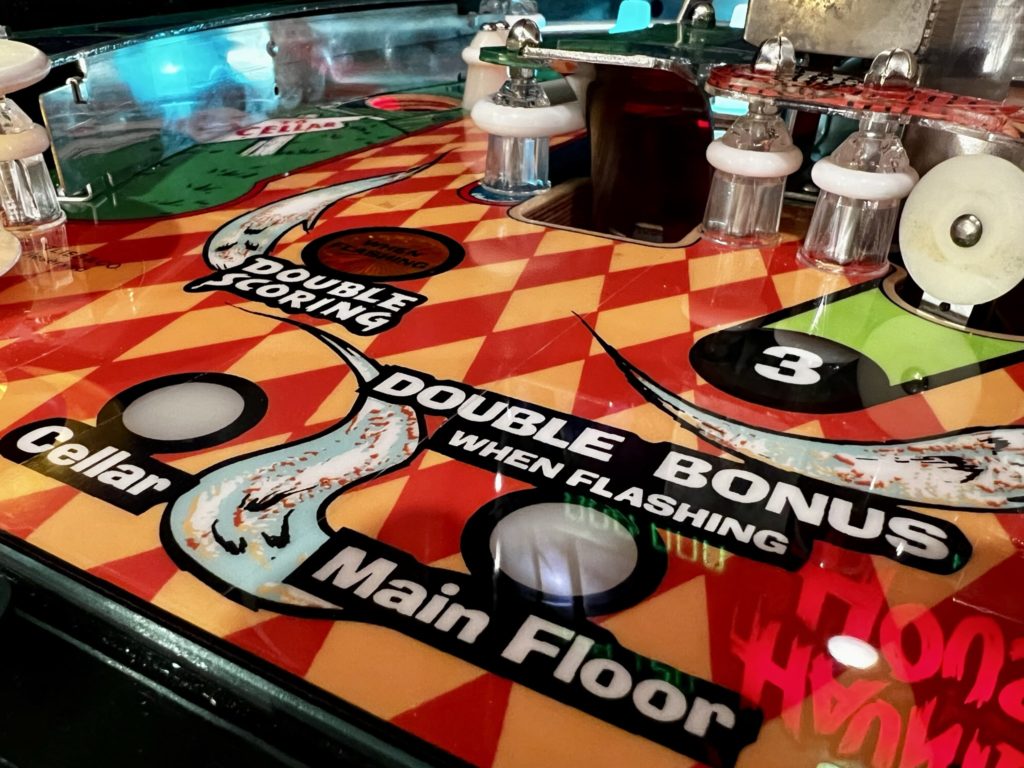
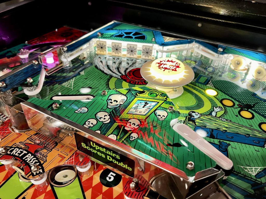
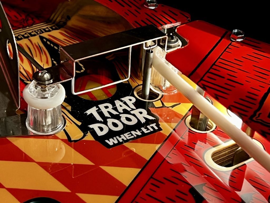
Gottlieb made 6,835 Haunted Houses with the first games hitting the streets on June 1st 1982. John Osborne is the game designer and David Thiel was the sound man. We have Richard Tracey and Terry Doerzaph to thank for the the stunning playfield and backglass art – it was retro (even for its day) and is beautiful to behold. It’s a system 80 widebody with a simple painted scheme cabinet. That is the only thing “simple” about Haunted House. It’s a complex and heavy beast of a game. It has 3 playfields: An attic upper playfield, a main playfield and a basement lower playfield. It has 8 flippers, 4 pop bumpers and 2 score display areas (one is for the bonus). It has 4 of the proprietary Gottlieb “kicker targets” and even has a mechanical “trap door”. It has a unique centrally located target that “swallows” the ball (and drops it to the basement) and 2 VUK mechs. When released it held at least 2 records – the first pinball with 3 playfields and the most flippers ever (8 total). It weighs as much as a Volkswagen and has the reputation (to continue the cargument) of a Yugo. At times it can be a challenge to keep running.
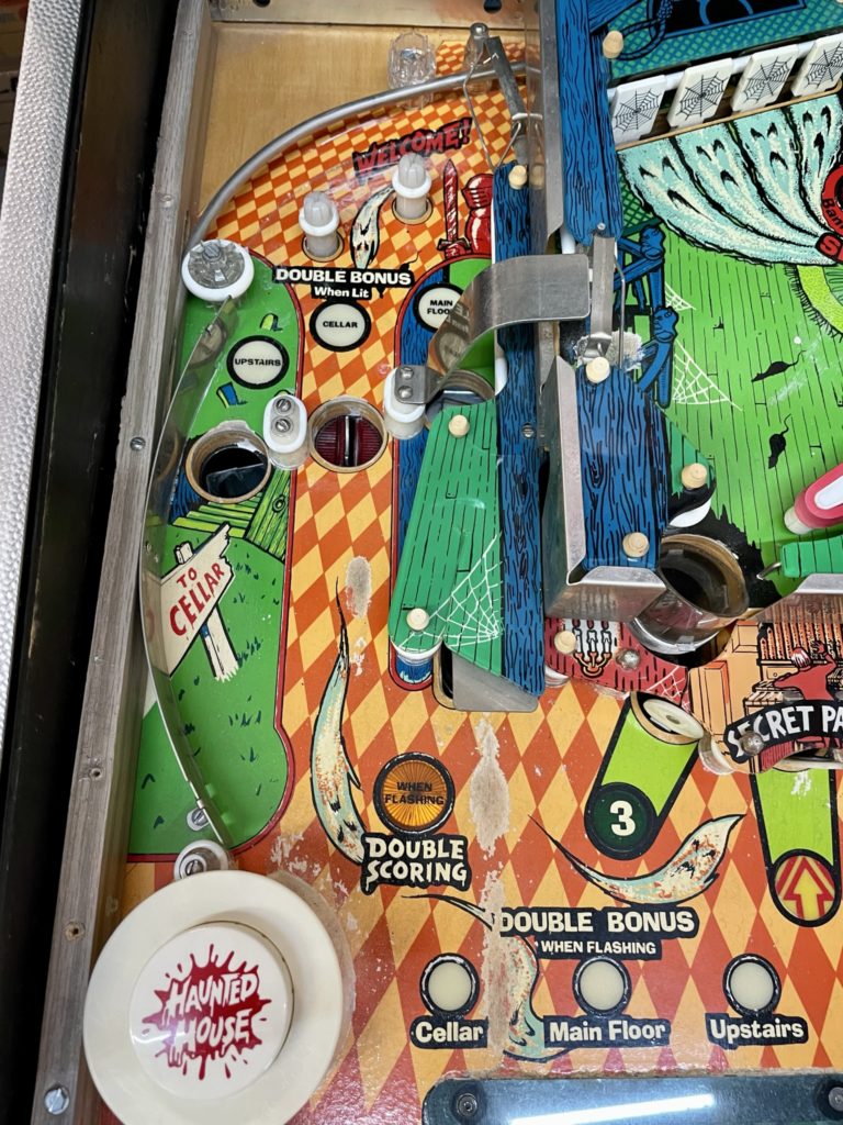
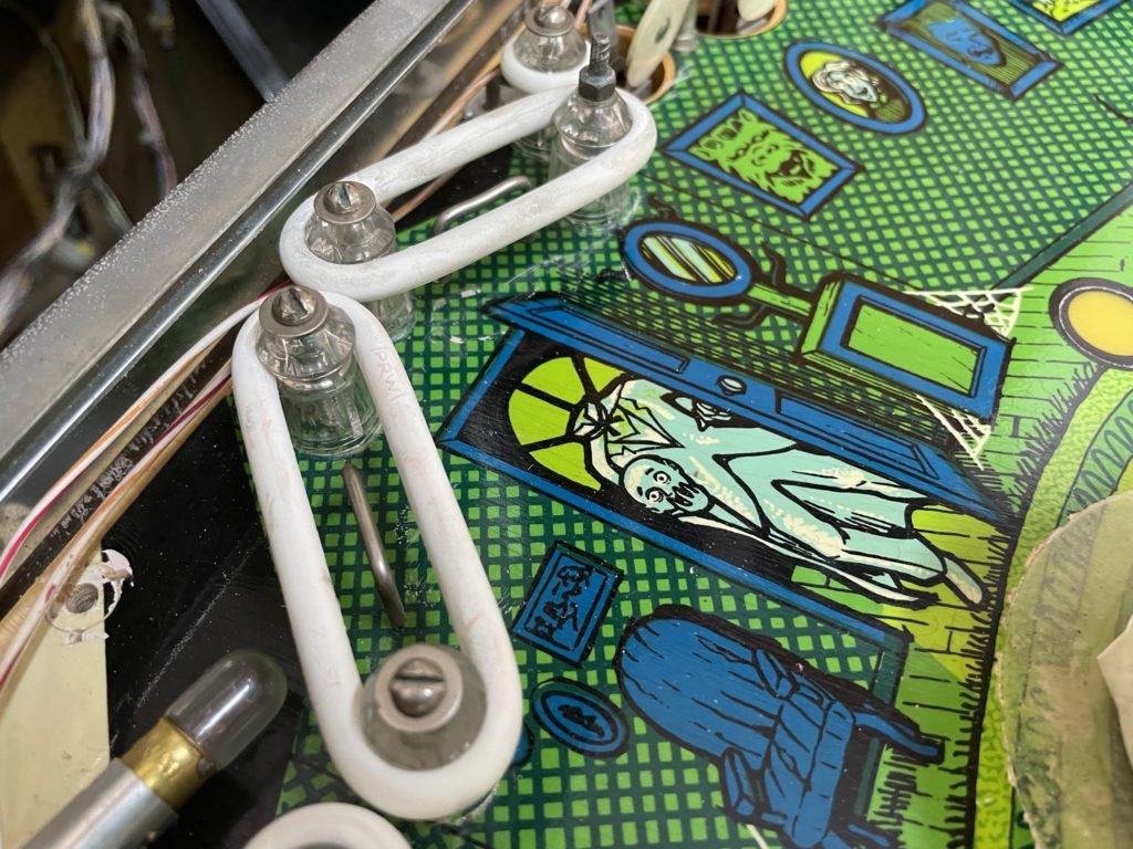
John Osborne is credited with nearly a dozen games – Volcano being another of his solid state designs. Osborne recalls how he came to build the Haunted House design during a TopCast recording a few years ago. He said he was made aware of a Bally game (Xenon) that had a plastic tube carrying the ball from playfield to playfield. This was some of the inspiration to create Haunted House. In response to the Bally Xenon game, Gottlieb leadership asked John Burris to design a 2 level game (he went on the design Black Hole), while John Osborne was asked to design a 3 level game (Haunted House). Kicking slings would not work due to the open window sitting in the middle of the playfield. John recalls the fold down drop target (and his subsequent patent on it) and how he purposefully placed it between 2 “normal” targets – to enhance the surprise! He also wondered aloud if the game ever made money for Gottlieb as it was so complex and unique in its design. He also squashed the idea that he ever planned to have a multi-ball in Haunted House. Due to the multi-level design, ball control and code management would have been almost impossible. It was fascinating listening to John answer the interviewers question concerning game rules and code. John responded by saying that he did not “recall how the game was programmed or the rules”. He went on to explain that during that time games were programmed separately from the the influence and impact of the game designer. He shared that this was a relatively new approach and one he clearly did not agree with. He revealed that Richard Tracey (the artist) came up with the idea of running light strings to highlight the lighting in the backbox. John recalled a device he “found” that resembled a trap door and asked the tool room team at Gottlieb to build a pinball based mech. This was the revised version that made it into the Haunted House game. He also recounted how the upper left of the game would likely be very dark. He knew he needed to address it and remembered that he had seen in prior games a “baby bottle” nipple shaped post that had room for a light in the middle. He went about designing his own version for which Gottlieb agreed to build out the tooling for it. The end result were the 2 “post lights” in the upper left corner of the main playfield. Listening to the interview I was struck by something that should have been obvious beforehand. The addition of the basement forced the introduction of the large transparent window into the middle of the main playfield. This forced John to make significant design changes to accommodate for that – one of which is mentioned above. Haunted House was John’s last designed game but he remained connected to pinball. Interestingly, he is credited with “saving the Gottlieb sign”. The one that was mounted on the factory. No small feat. Follow the link for an interesting story and some pinball history.
http://www.pingeek.com/gottlieb_sign/gottlieb_sign.htm
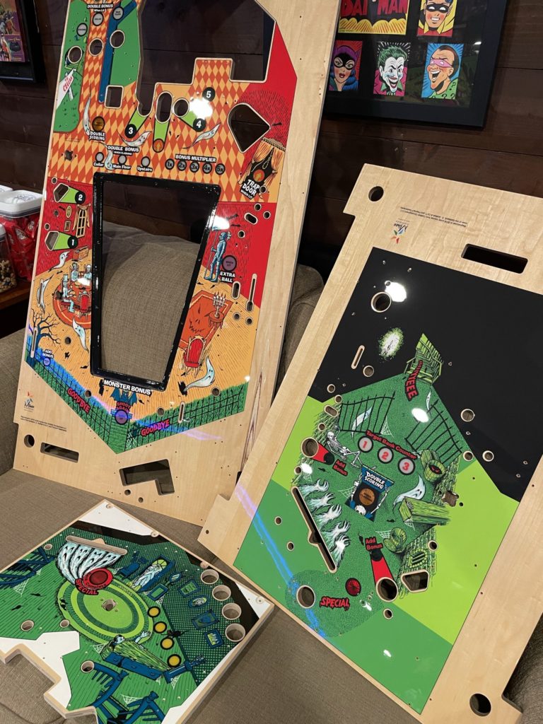
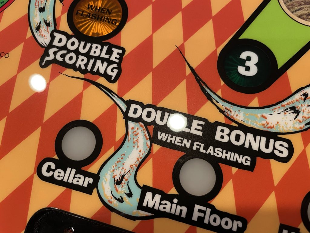
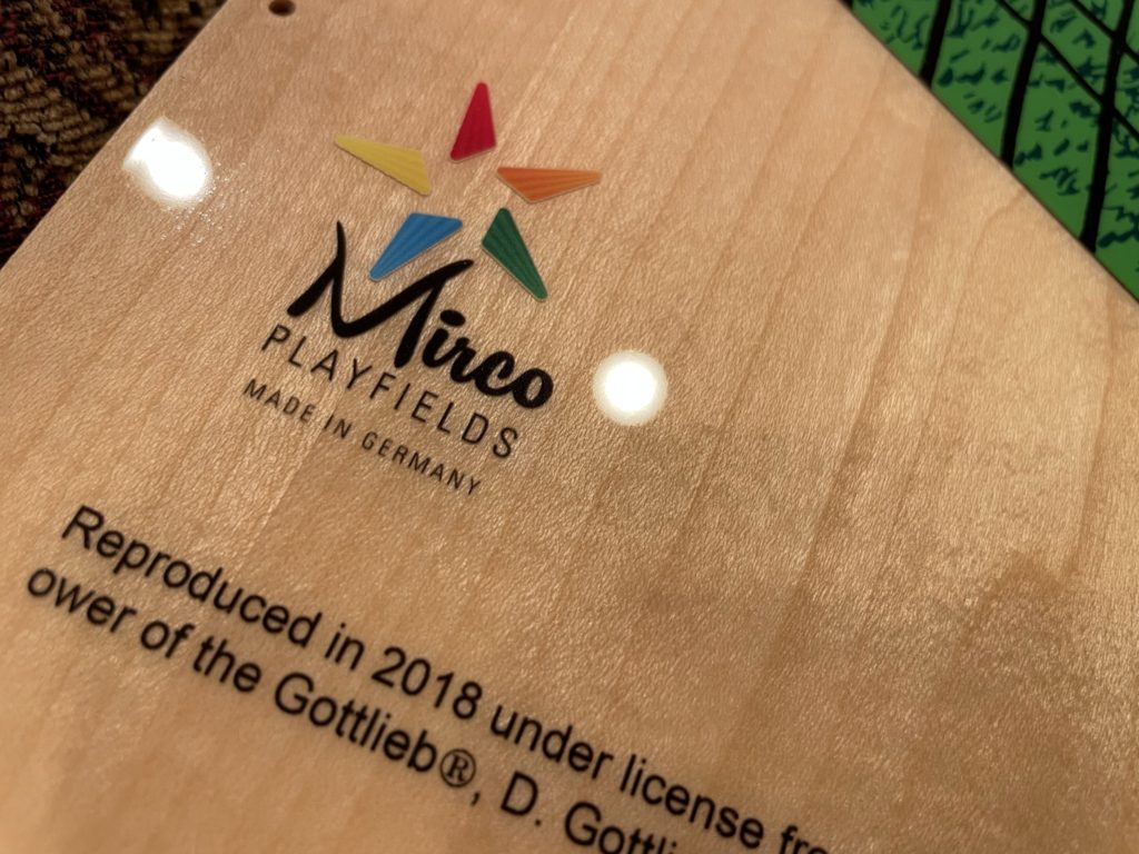
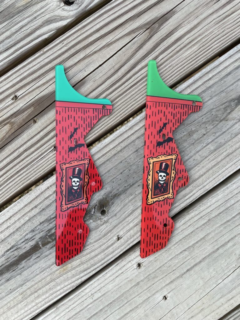
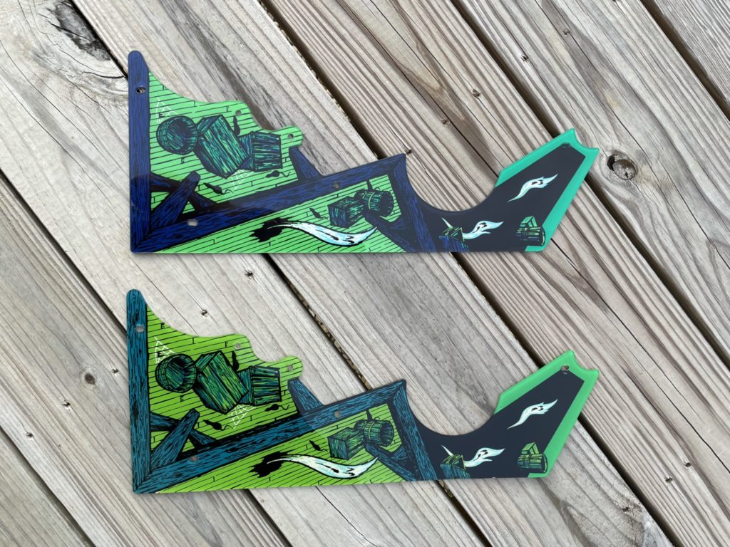
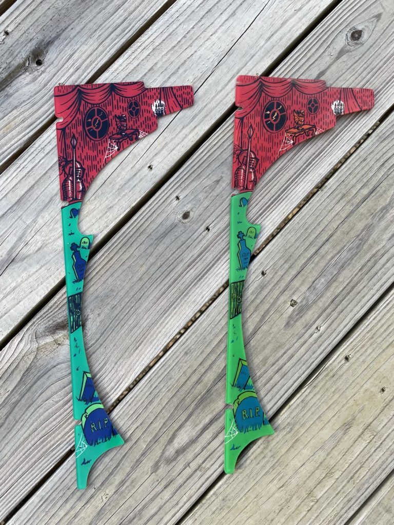
I got back home and immediately went to work to find and order the 3 Mirco playfields. The first few searches turned up pricing of over $1,500 dollars and was a bit of a shock to the system. I finally went to Pinside where Mirco advertises and found the complete set for a more reasonable $1,100 delivered from Germany. Next I had to find a new plastics set. Unfortunately, none existed in the US so I ordered the plastics from overseas and had them shipped to my UK address, then forwarded to the Loft here in the good ole USA. Finally it was time to scour the top and bottoms of the old playfields to put together my order from my friends at Pinball Life, Marco and Pinball Resource. You can see in the images that the reproduction plastics vary in print and color from the originals. They are not perfect and lack some detail but if yours are broken …
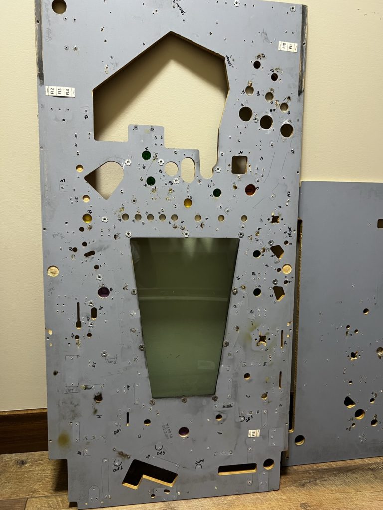
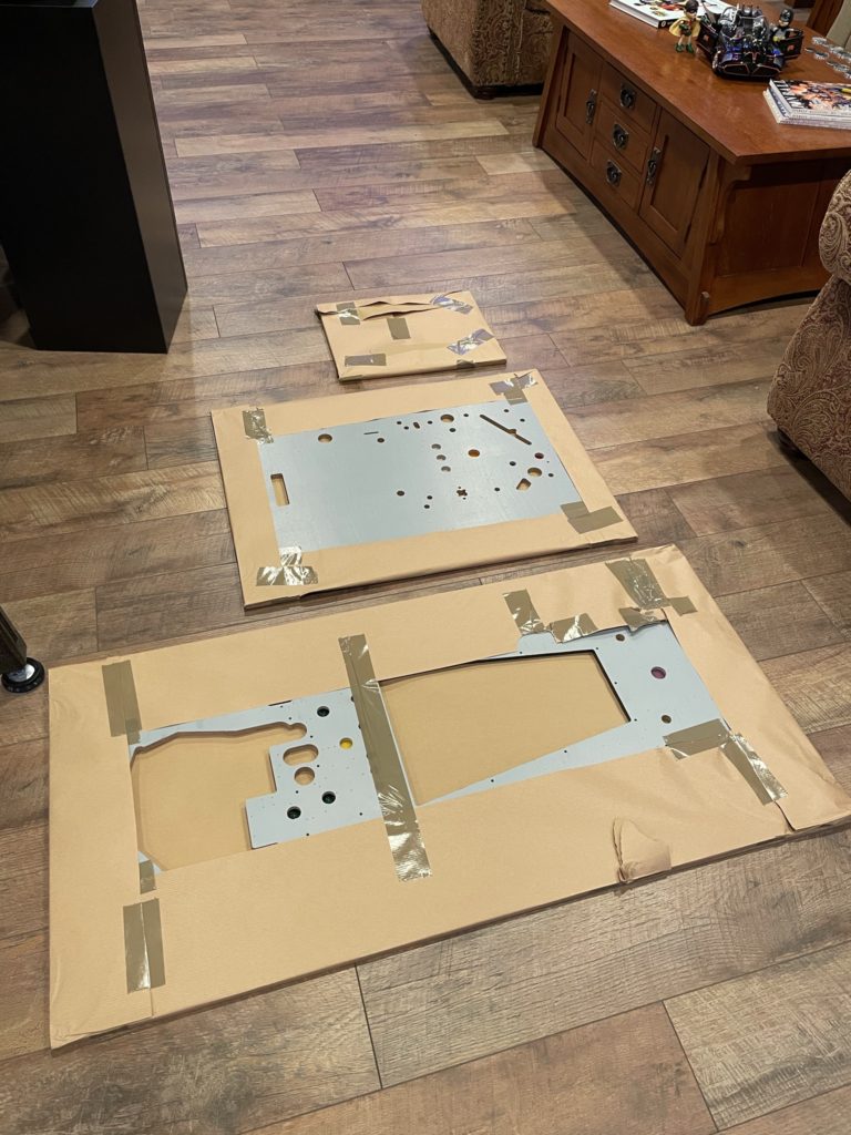
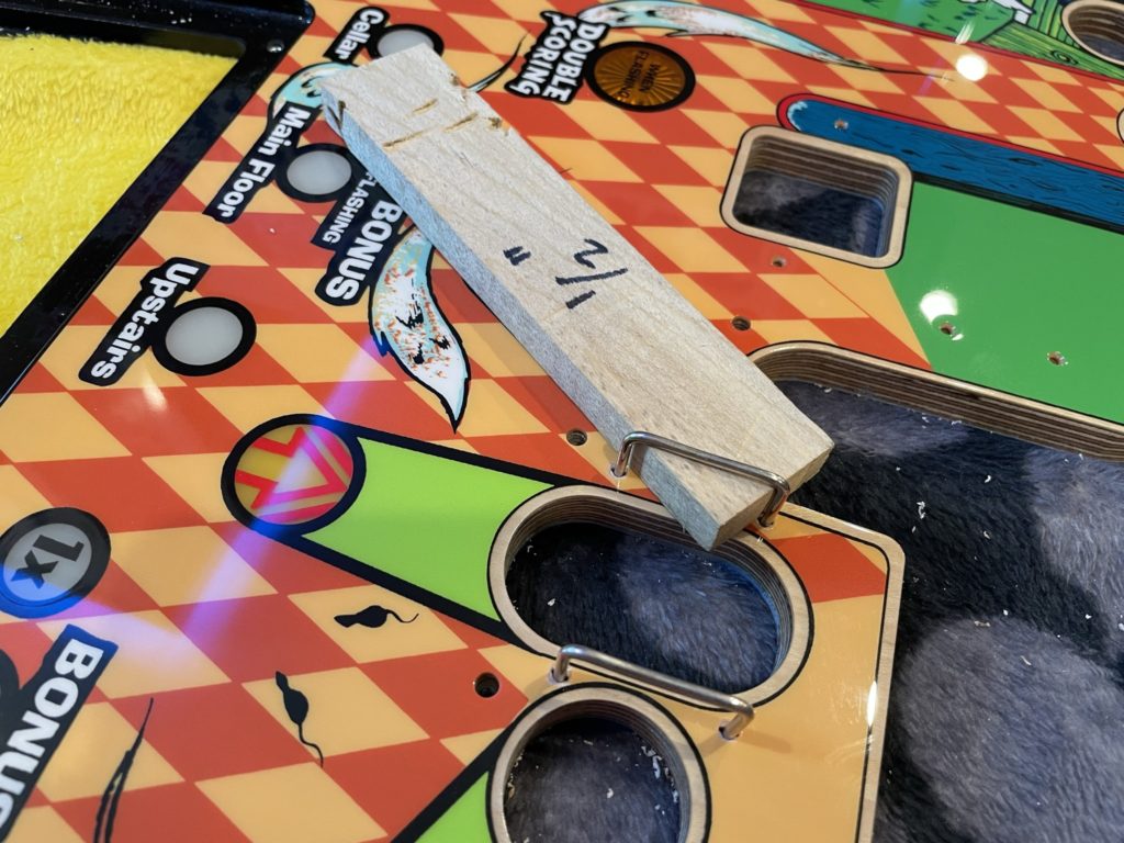
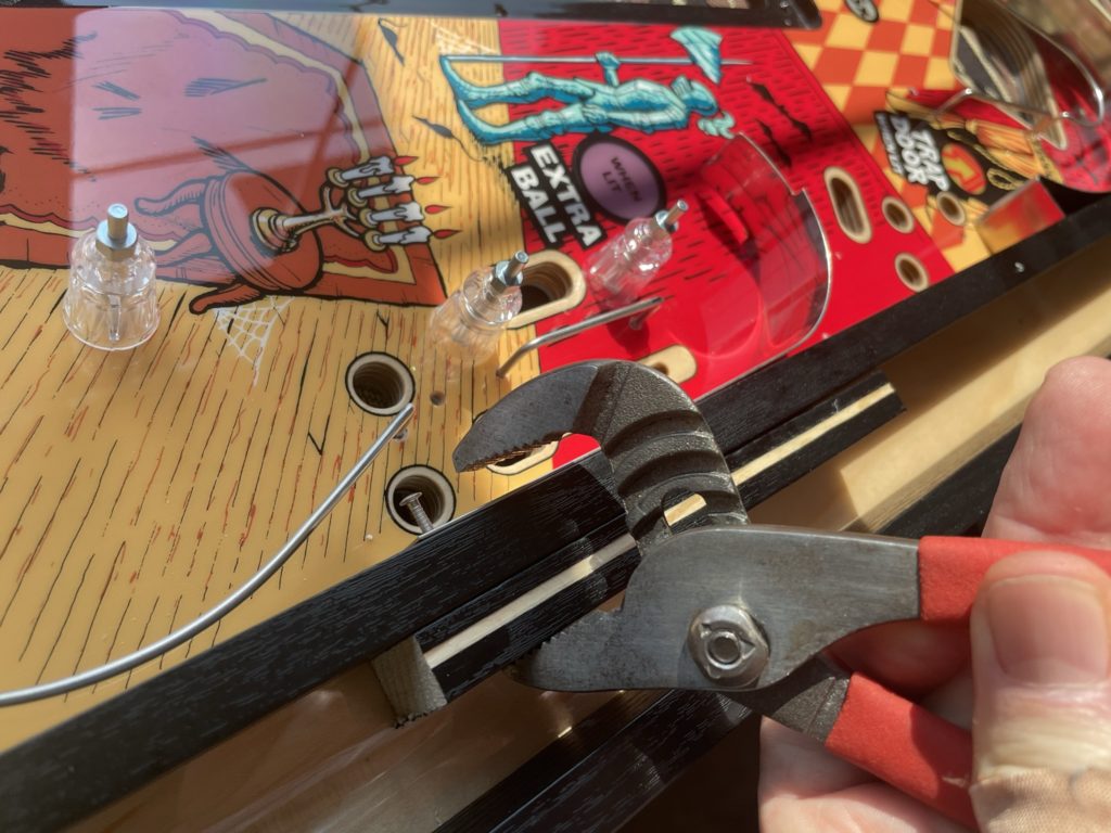
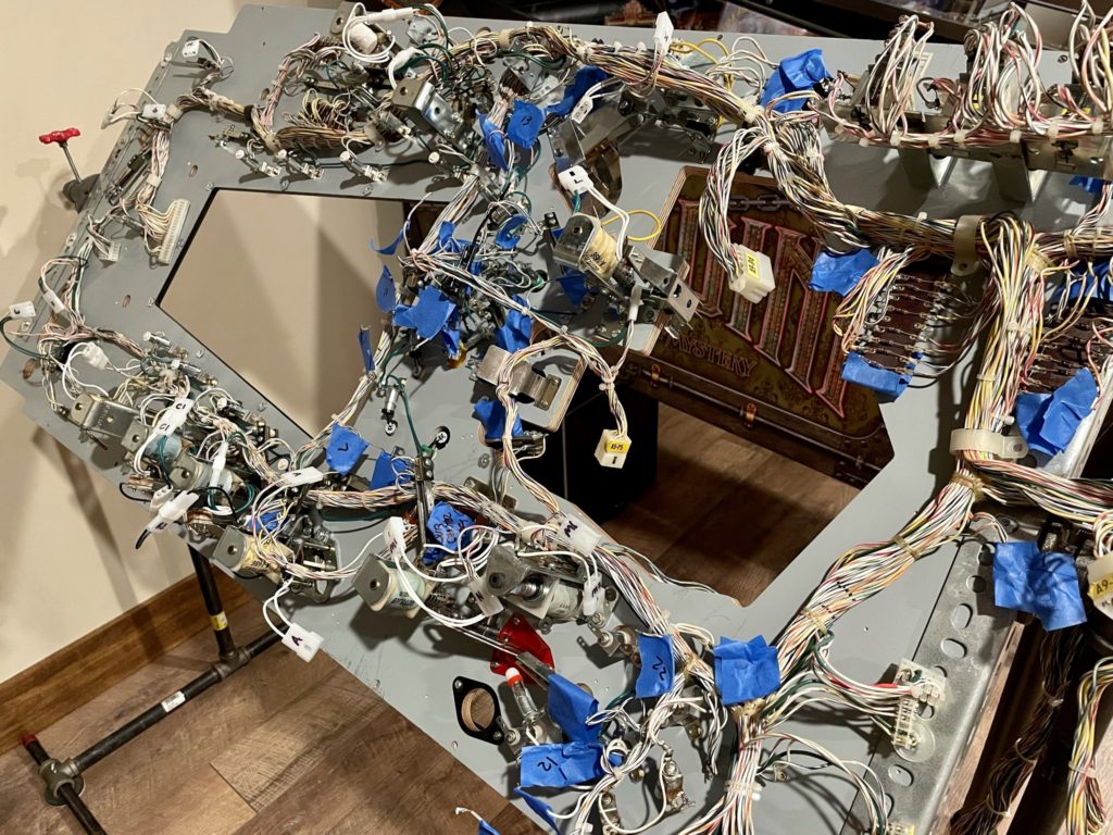
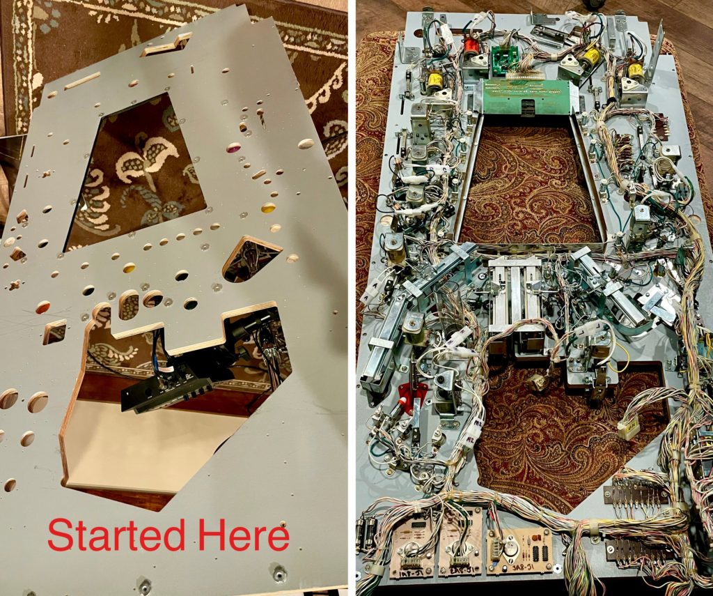
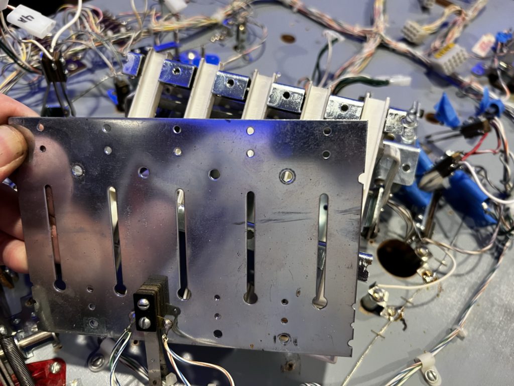
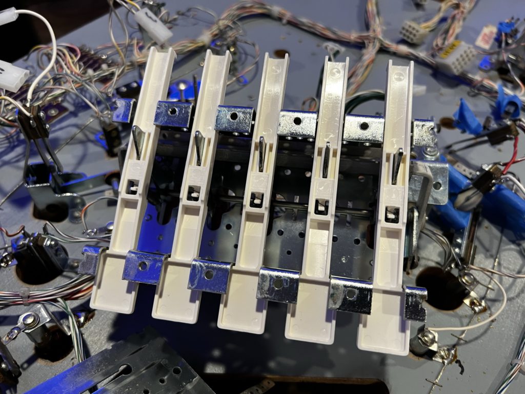
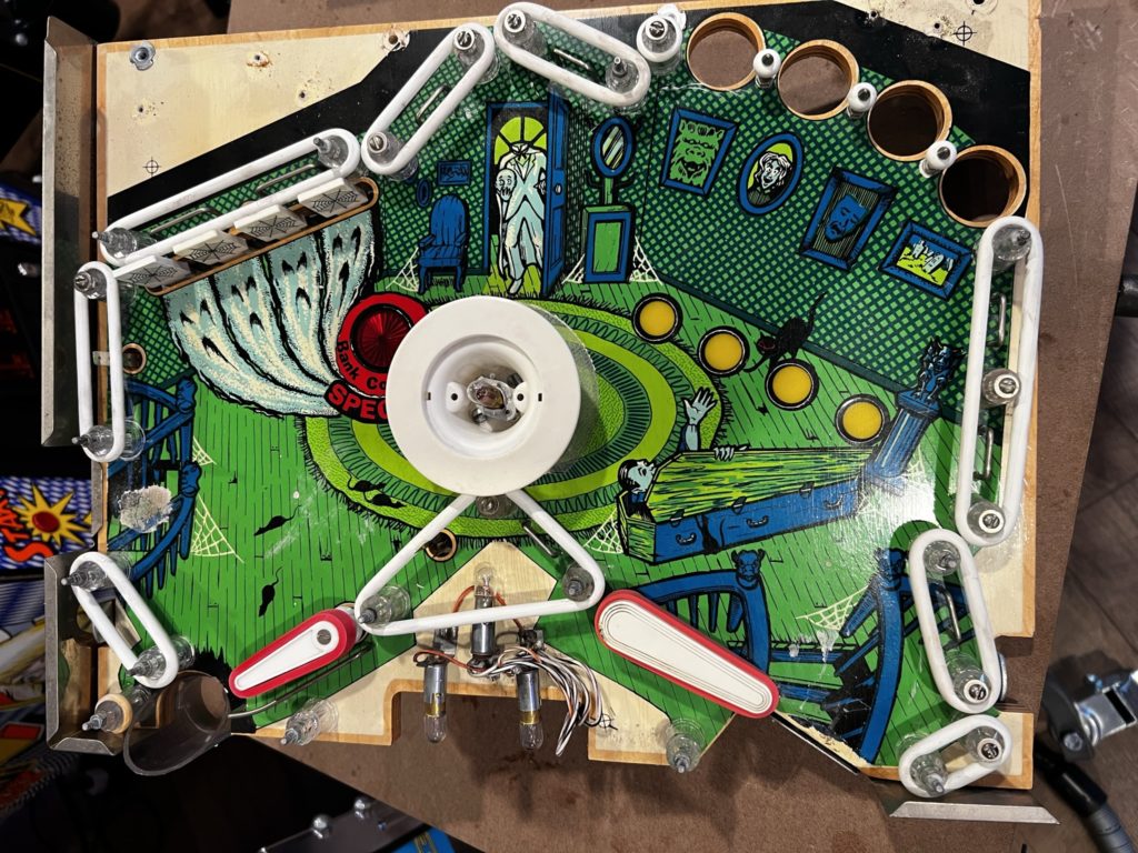
It was time. Time to really kick the process into gear. That moment always begins with stripping the top of the playfield and taking careful notes and hundreds of pictures along the way. I bagged all parts and took photos from many angles before removing them. The plastics on the topside of the main PF were in great shape (except the “Secret Passage” one which is always destroyed). Once the plastics were off, I removed all the star posts, then used a small flat bar and a block of wood to gently pry up all of the (many!) wire ball guides in the game. I unplugged all the of connectors from the main PF to the lower PF, the cabinet and the circuit boards in the head. I then removed the small upper PF (easily accomplished with just 2 nuts) and followed that by removing the main PF from the cabinet entirely now that it was no longer plugged in to anything. Removing the flat metal ball guides was an interesting challenge. They are held on with specialty ribbed nails directly pounded into the playfield rails. After posting a question to Pinside on “how to remove them” I settled on using a stiff putty knife to pry in behind them until the head was exposed enough to grab it with some pliers. I was able to get the nails out with little damage to the rails. I was MORE concerned about damaging the guides and nails as I had new PF rails already in hand. The guides are all drilled for 2 nails per point of contact but interestingly enough, only one of the nails are used because one of them would contact the ball during travel so it was left off at the factory. I spent $40 buying new “eustachian” style nails from Ebay only to later simply re-use the existing nails as they were in good shape after extraction
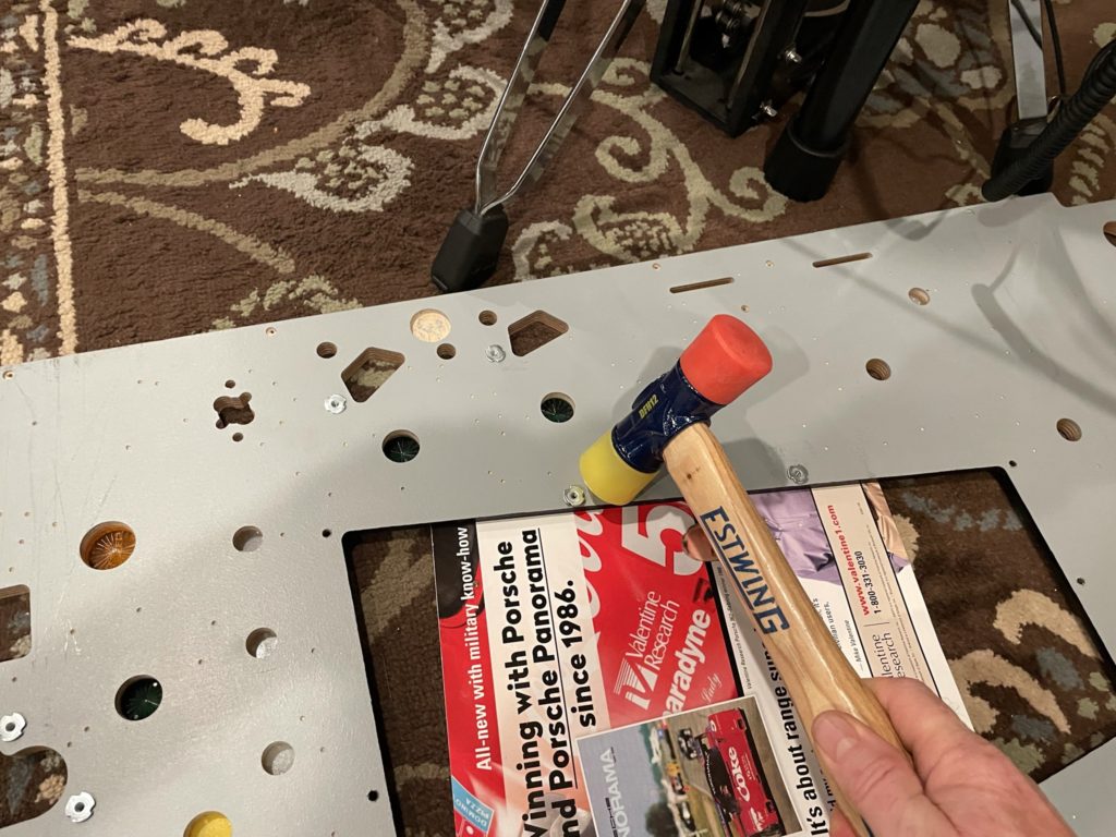
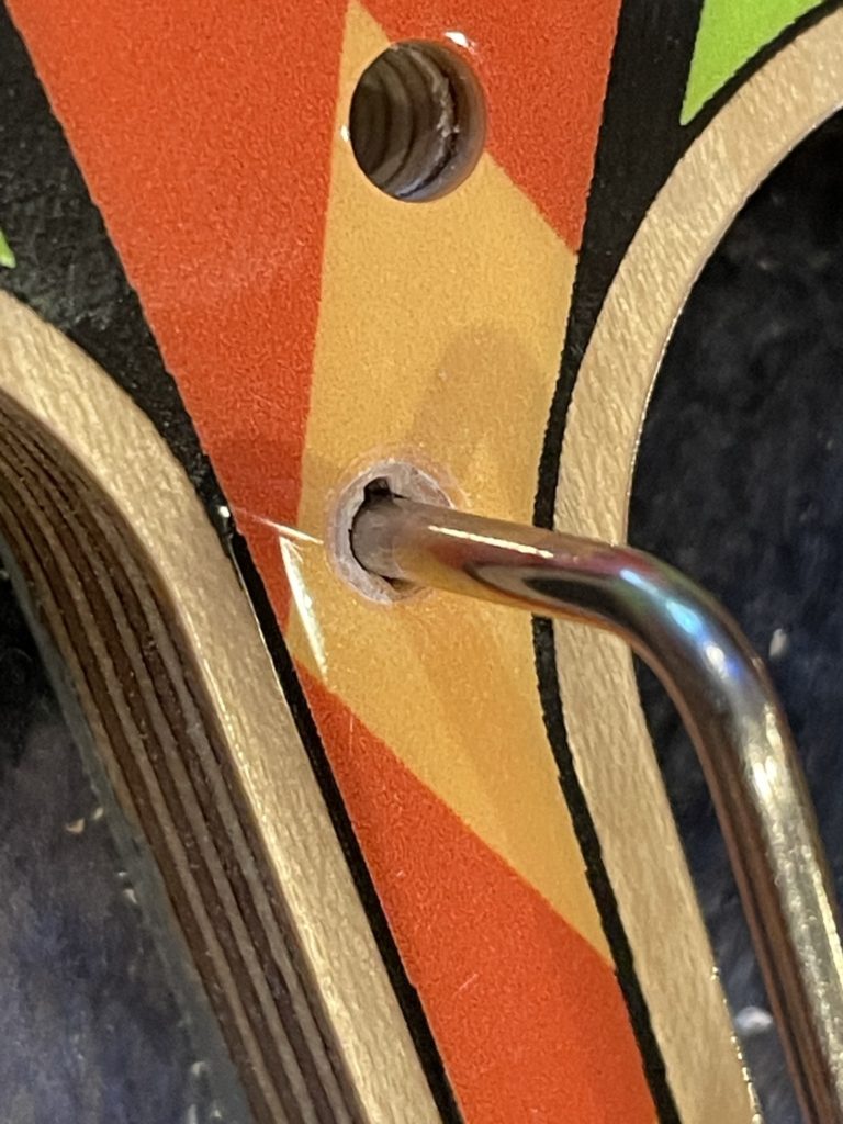
With the main PF now out of the game and baggies full of parts sitting everywhere, I turned my attention to the brand spanking new (now completely empty) Mirco playfield. I started on the back adding the T-nuts as they require using a plastic face hammer to pound them in. Next it was on to the wire guides. I use a 1/2″ thick block of poplar as a guide to seat the correct depth. I first reamed each hole out with the hand tool in order to remove clear coat around where the wire intersects the playfield. This prevents the wire from potentially lifting the clear coat as you pound them in.
Speaking of pounding … the ball guides turned out to be VERY hard to pound in. I should have sharpened the ends because in all of the “violence” it took to seat them to the proper depth, I introduced some hairline fractures into the edges of the clearcoat on 3 inserts. I’ll be honest, when I noticed them (days later) I was pretty upset. I took an hour to cool down and simply set it aside to continue the mission to swap the playfields. The damage was small. The clear was not lifting (and would never lift later). On 2 of them you could not even feel the fracture with your fingernail (was under the surface). I would add a pre-cut mylar circle to each insert to ensure no chipping would occur at the fracture points (I did that) and move on. So I did. After all … I have 40 other machines that at any moment have SOMETHING wrong with them mechanically or cosmetically. The minute you start playing one is the same minute they are no longer perfect. The playfield looks amazing, and I would have to point to the spots for you to see them and game play is not affected in one bit. Time to get over it.
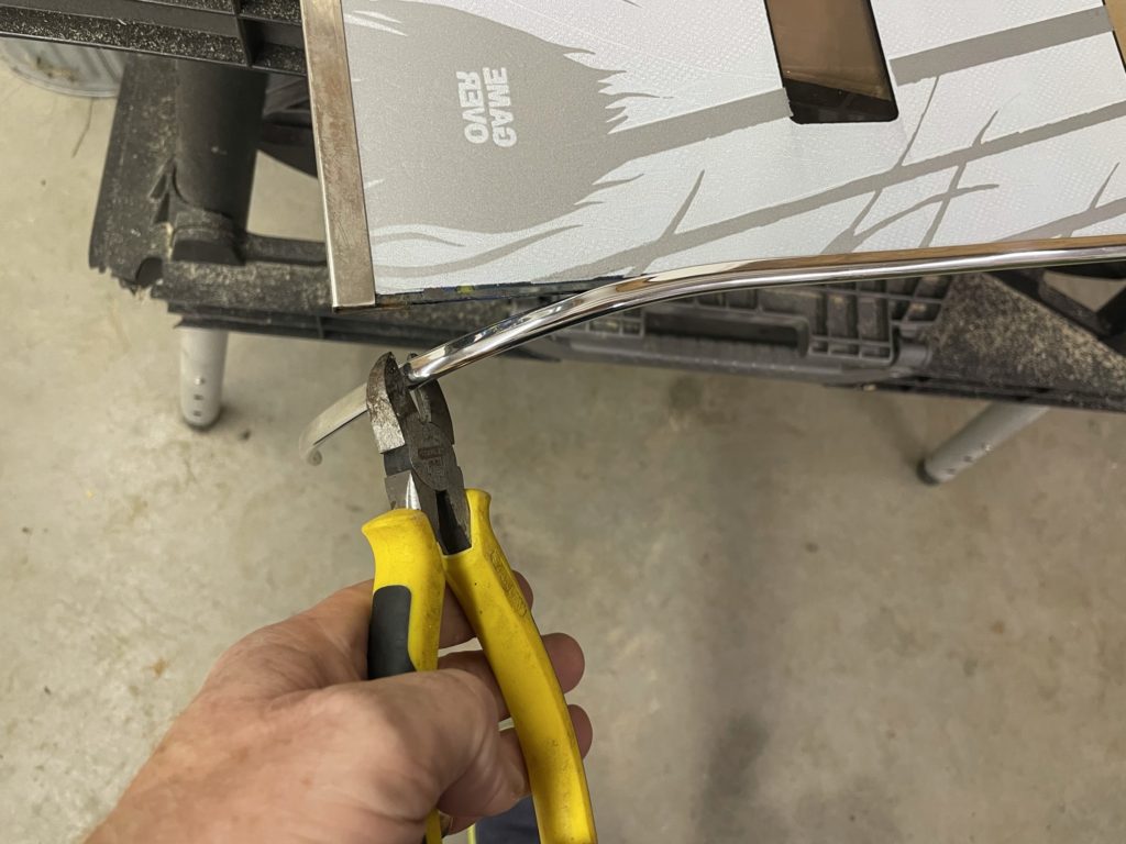
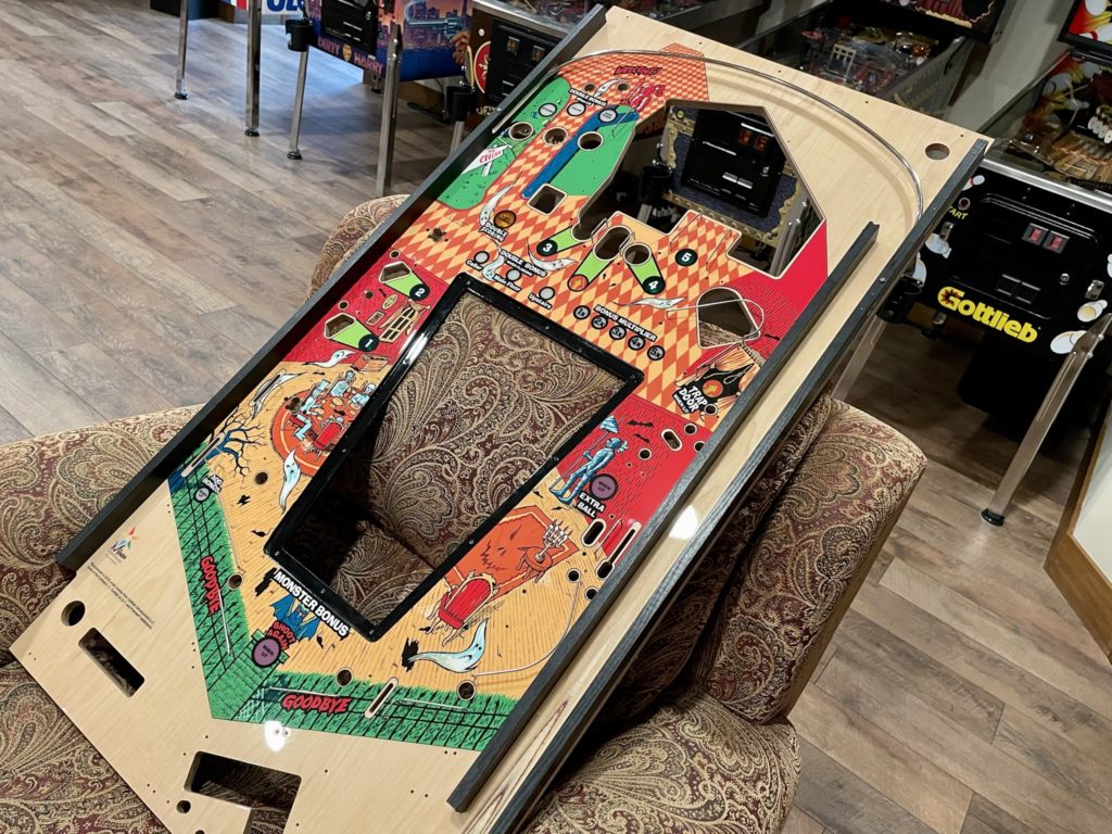
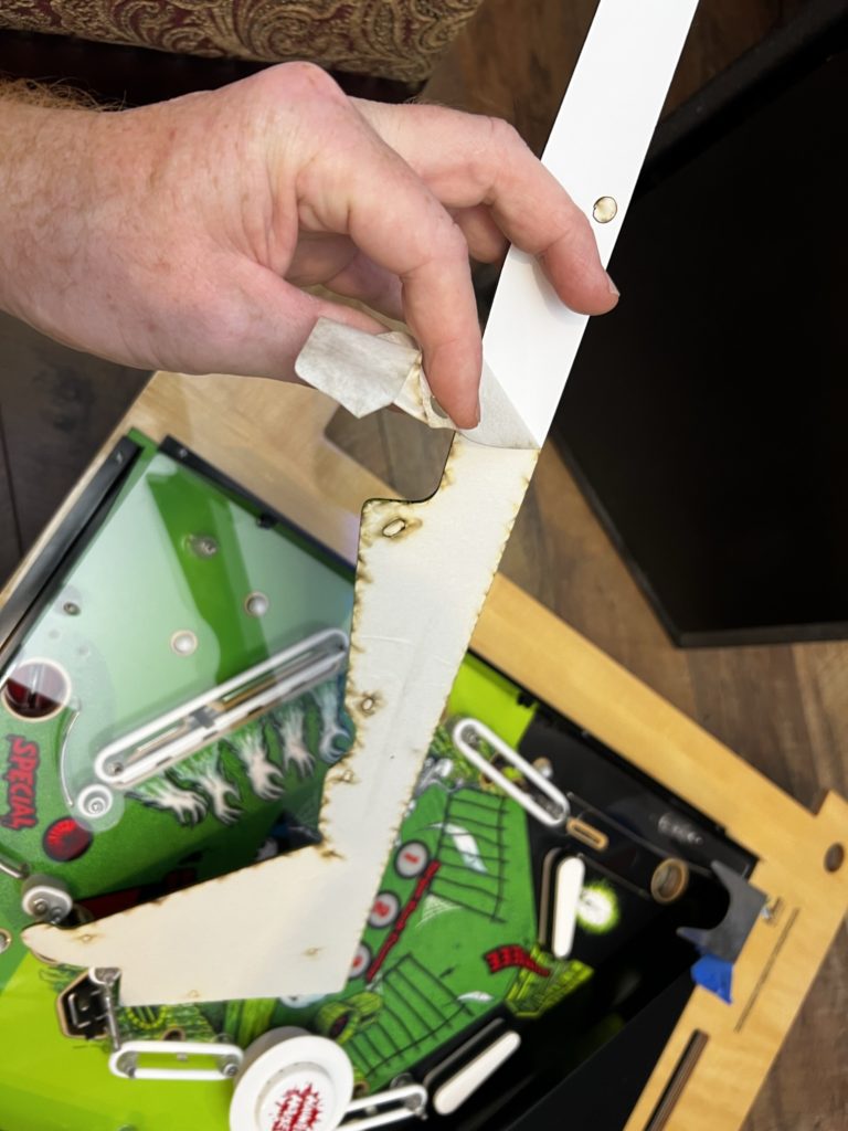
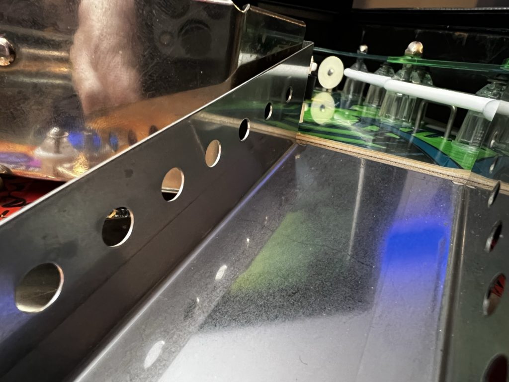
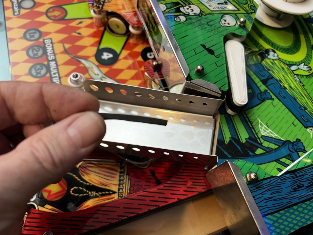
Next phase was on topside of the new playfield. I wanted to build new black colored rails as a replacement for the beige colored ones. I saw this done on Pinside by Chris at HEP and really liked the look. This effectively removes the beige/bland stock rails and replaces them with a nice “haunted house style” black. The contrast is perfect for this game. I ordered the blank “sticks” from PBL and cut them to length, then drilled out access holes in order to jigsaw the slot out that holds the upper ball rail wire guide. Installing required looking at the pics I took to ensure proper starting/ending spots – remember these are new rails and as a result they did not have drill holes in them for placement reference
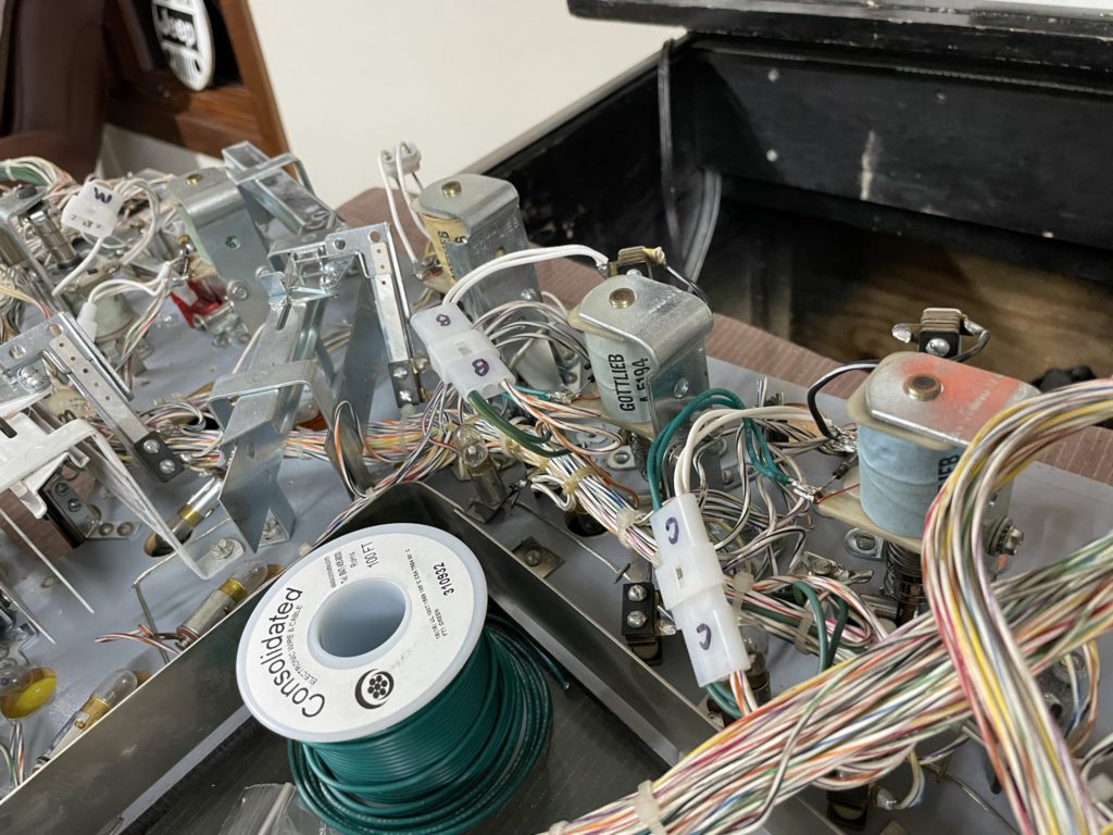
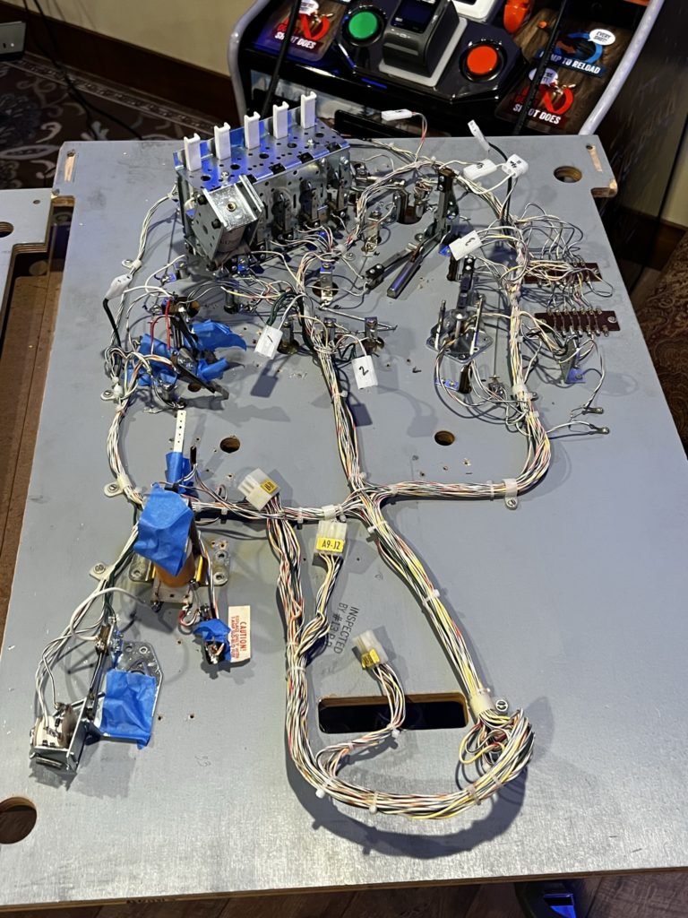
Back to the old playfield now in order to add Molex connectors to all major mechanisms. Again this is a copycat process I took from Chris at HEP. Others poo-poo the process and say it’s not necessary. I think they focus on the fact that many times this is done with the reason that “in the future” you can remove mechs quickly for service or repair. This was NOT the reason I did it. I just wanted a way to get the mechs off the playfield and away from the already too complex wire harness, switch and lamp wiring. For THAT purpose it was extremely helpful and I think took the swap from “impossible” to very doable. This is especially true for a game as complex as HH.
So I marched on. The pops, scoops, slings, flippers, kicker targets etc. all had molex connectors soldered to both the harness and the mech to allow me to easily disconnect them from the PF harness, making it much easier to first remove the mech, then to remove the harness and solder it back to the new PF later.
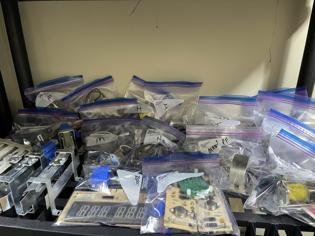
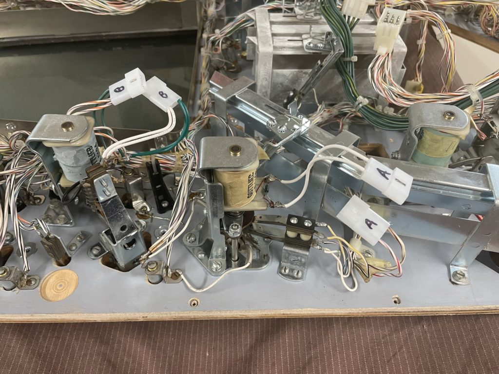
After building and soldering in the connectors, I removed all the mechs/solenoids from the backside of the playfield, along with the mounting screws and dropped them into a quart baggie. Each was labeled A- N as were the Molex connectors. I even ordered wiring that would allow me to build the molex connectors in a consistent manner, using green where Gottlieb had and plain white wherever they had used a base white (then added a colored stripe). I could have added a sharpie stripe to each of my plain white wires but chose not too. The molex connector only fits one way and I did not concern myself with the need to make it “match”.
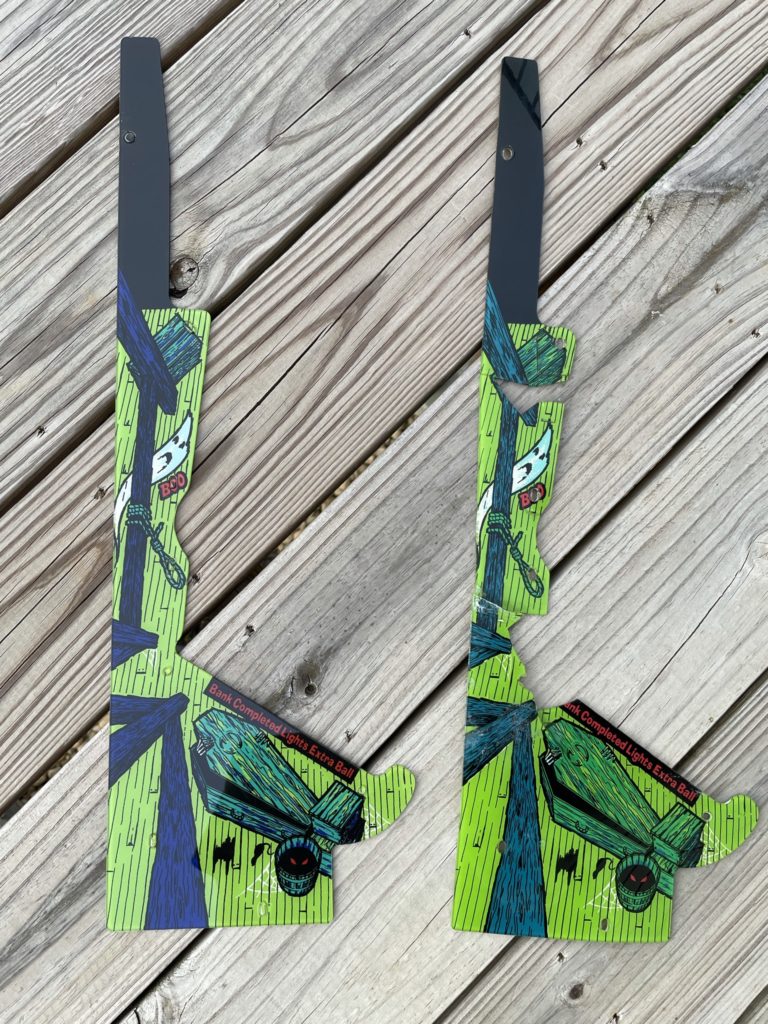
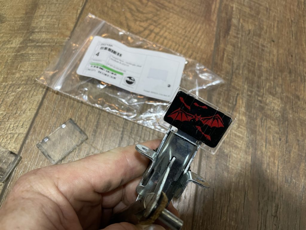
While waiting for parts, I noticed the “Secret Passage” plastic that sits at the middle/top of the main PF was broken (as are 99% of them in the wild).I spent a few hours in Photoshop, recreating the artwork from the broken pieces. This involved scanning in the pieces on my flatbed and simply filling in the missing art where the plastic had cracked. There was also quite a few areas of damage and scratches that needed to have touch ups completed. I completed all of those in about an hour. I then did a test print and it came out really well – nice colors and the scale was correct. I have the commercially available protector that I will install after I create the new full art plastic
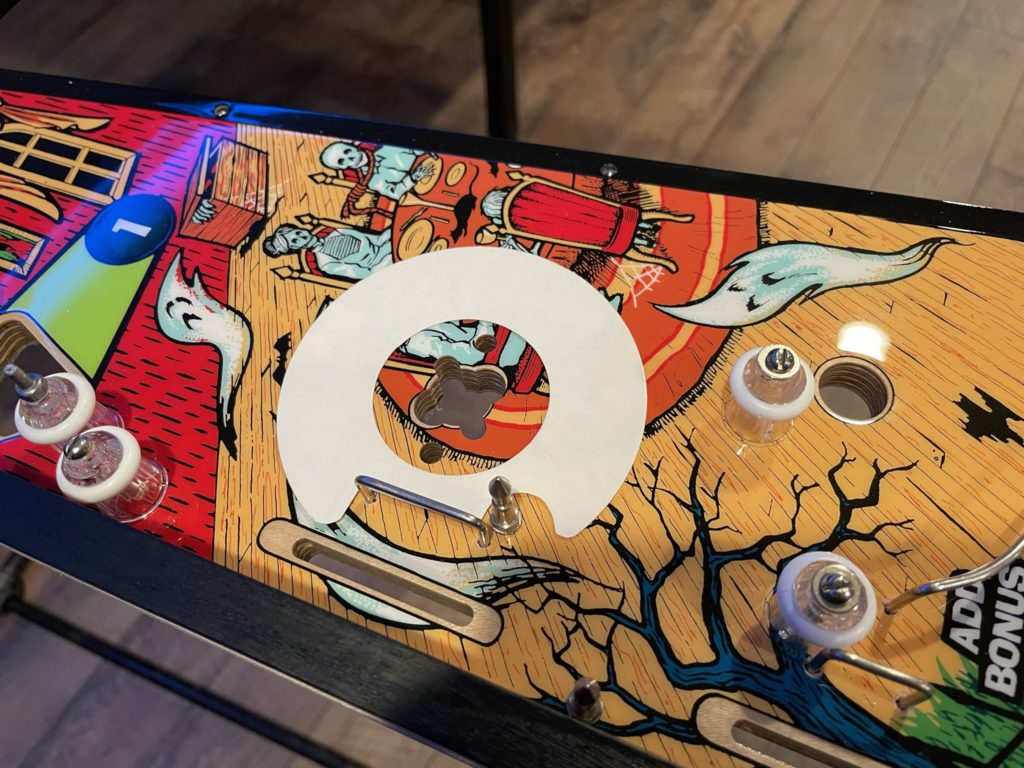
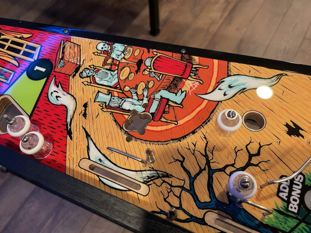
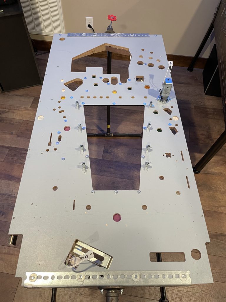
Back to the top of the PF it was time to prepare to add the Pops. My prior experience with installing pops (Bride of Pinbot, Harlem) was the process of hammering in Pop nails. I was surprised to see that Gottlieb did it differently and in a way that did not use a hammer or pop nails. The Gottlieb install involves the use of a pop bumper backing plate to mate with 2 machine screws that penetrate the pop body and are then mated into the plate on the bottom of the PF. Not sure if one is “easier” than another OR what one is more robust from an engineering perspective, but the Gottlieb system works and other than some “two sides of the PF” juggling at once to get those 2 machine screws mated to the base plate, the install was straight forward. To prep for the Pop installs I laid down mylar discs. I used the adhesive style as the Gottlieb ones (loosely installed) had a reputation of grinding the playfields over time. As I shared previously, it was at this point that I added 3 small mylar spot circles on top of each of the inserts where I had introduced hairline fractures while hammering in the ball rail guides. Once installed both the fractures and the mylar were virtually invisible
Before adding the mechs or large wiring harness back to the new PF, I had to add all of the new lamp sockets and the 5 volt power wiring. Gottlieb, like many others, used a bare wire that was stapled to the bottom of the PF. As I did in my Harlem restore, I chose to use an insulated wire. The other wrinkle was that because there were no 2 terminal sockets available for some of the lamps, I had to employ “solder tabs”. Wonderful, cheap and highly effective, they allow you to solder to the “body” of a single terminal lamop socket in a clean and functional way. I added all my new lamp sockets and tested each to ensure I had all wires going to the appropriate terminals. The testing part turned out to be important as I was “mixing” twin terminal sockets with singles – it’s easy to make a mistake and solder your 5 volt supply wire to the center terminal of a twin terminal socket. A simple check for continuity using a DMM saves a lot of headaches down the road. Remember, these wires are virtually buried under a mass of mechs, switches and wiring harness once that stuff is all installed. Got to get it right the first time. Oh, and before I forget, add the LED’s as soon as you are done with this part. You have even choose to add them before mounting the sockets. They are a major pain to add later
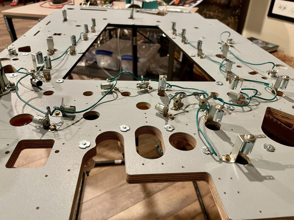
Now it was time to add back all of the remaining mechs. I did this BEFORE adding back the wiring harness as the mechs require quite a bit of “fitting finesse”. The location of the armatures and solenoids determine how smoothly they move when activated and you simply need “room” to pull this off. Once the mechs are installed, the harness will lay naturally in between them. I started with the pop bumpers as they are the most complex. I completed the first one rather quickly and moved on to the second only to discover the pop bracket and much of the associated hardware was a McGyver fix that an operator had pulled off years ago. The bracket had the mounting holes all “yoked out” just to make it fit, the fiber and metal plunger centering pieces were not correct and neither was the plunger. I jumped on Ebay and ordered an pulled pop bumper from a Mars God of War to replace it. That part came quickly and I added the second pop bumper as quickly as I did the first.
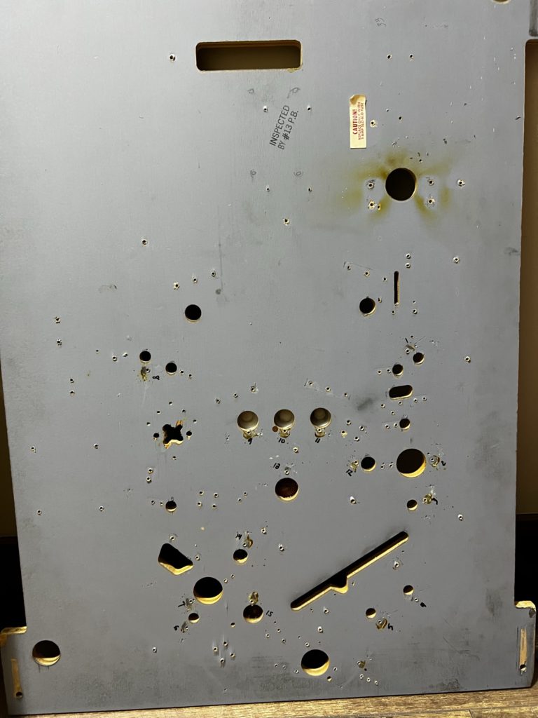
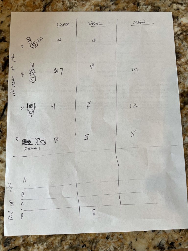
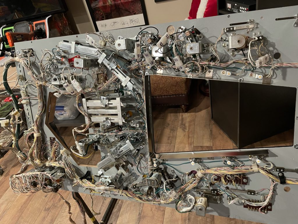
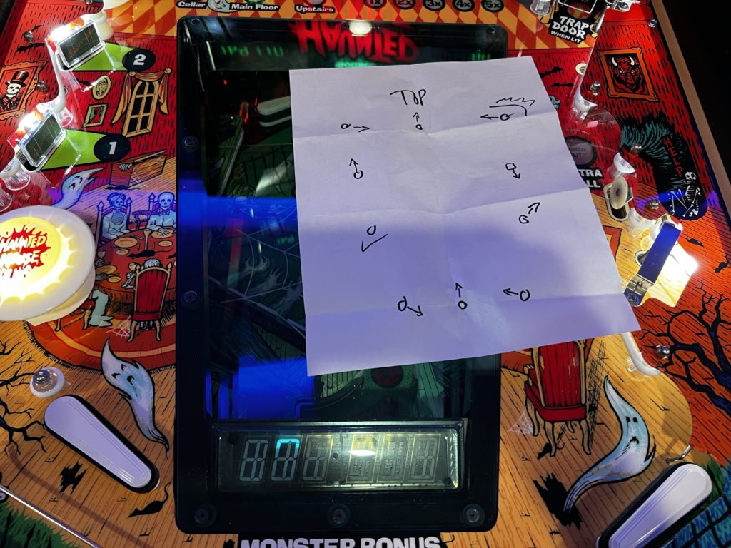
The process was simple, even if the work was tedious. I grabbed the first baggie labeled “A” and installed a kicking target mech and worked my way around the PF until I had gotten all the way to “N”. I skipped the 4 flipper mechs as they could be installed almost last and needed to be rebuilt. I replaced the coil sleeves on every mech along the way and in the case of the kicking targets, I replaced the high voltage switches as well. 3 or 4 hours later all of the mechs were bolted down and awaiting a wire harness to be attached to. I moved to the back side of the original PF to begin the process of documenting the wiring color codes for all the GI and controlled lighting circuits (see notes at end of this post for wiring details)
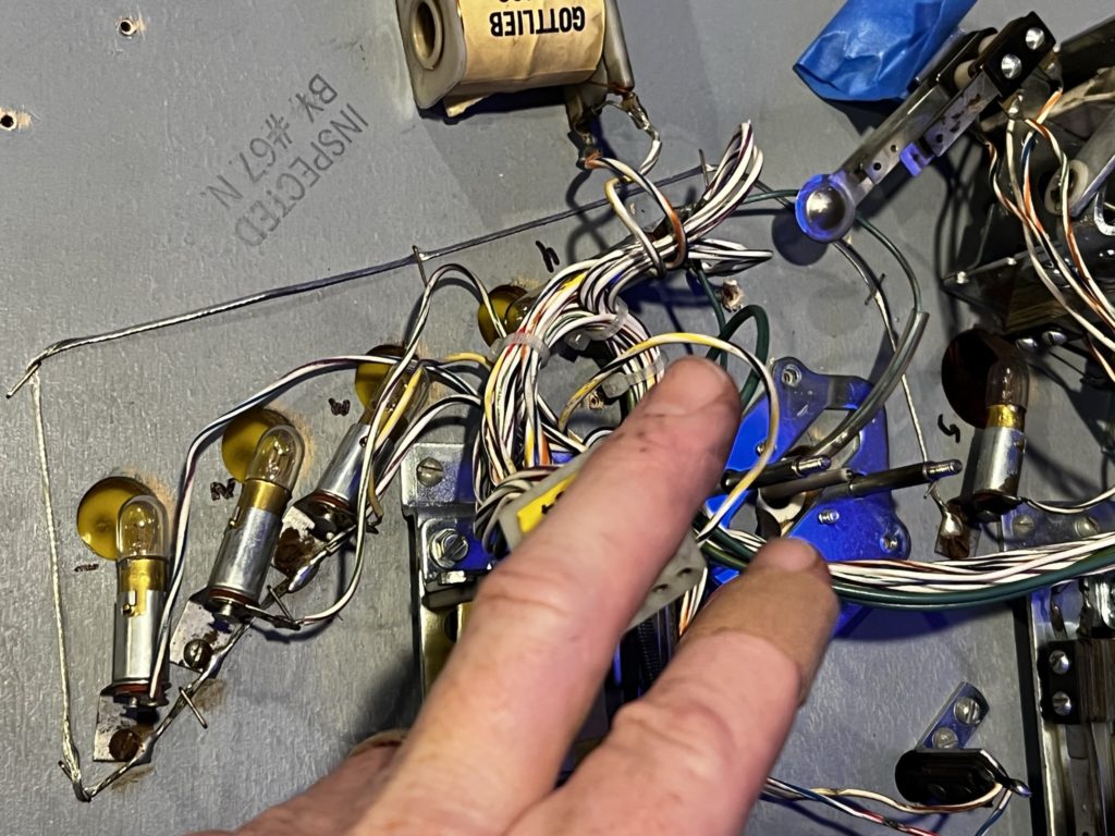
I used a sharpie to assign a number to all of the PF lights and then captured an image of it, while writing down what color/stripe went to each assigned lamp number. Once completely documented, it was just a matter of a few minutes to unsolder all the signal wires to the controlled lamps. Unsoldering the larger voltage supply wires took a little longer as they were attached to the lamp bodies and by nature were acting a pretty good heat sink and reducing the effectiveness of the iron.
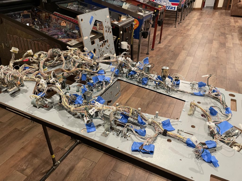
With the lamps all free, I now had to unscrew and blue tape mark all of the switches, stand up targets, fuse blocks and harness clips – my plan was to leave ALL of them still attached to the harness. This part was slower going but not terribly so – and it went off without a hitch. I would pull the switch, wrap the original screws with it and mark it with the corresponding number on the PF. This process also included pulling the metal subways off the PF and first disconnecting the switches that were mounted on them. In a few hours total, the harness was free from the old PF. I carried the now disconnected harness up to the Loft to gently lay it down on the backside of the new PF sitting on my rotisserie. One of the key things I had done in prep for this moment was to use a sharpie to draw a line (directly on the wire harness) on each side of every harness clip. That way, if the clip moved as I was transporting the harness, I would know it’s original location. Assuming the dimples on the backside of the new PF were accurate (they were), this allowed the best chance of getting the harness placed exactly where it needed to be to allow perfect connections to the new lamp sockets. The plan worked and in the entire process I only had one wire that was a “stretch” to fit.
Installing the harness to the new playfield went WAY faster than I anticipated. I’m guessing that it was no longer than 4 hours in total – maybe 5. I did the work over the course of 2 evenings. The process is NOT simply soldering it back in. Every time I came to a switch, I cleaned and gapped it and made sure the gap was “functional” post install. This saves a ton of headaches down the road. I started soldering at the least complex area of the PF (the bottom) and worked my way up. The last few bits to get done were the metal subways and the metal frame parts around the basement window. Nothing was difficult or extraordinary about this part of the process. Lining up the subway below the trap door was tricky but I had excellent pictures and some measures I had taken prior to removing it. I would suggest to anyone to do the same. I guess the high level process for those of you all attempting the same type of work is to do the work in the order as follows:
- T-nuts hammered in
- Ball guides hammered in (topside)
- Lamp sockets wired in (just the 5 volt wire)
- Mechanism/solendoids mounted
- Wire harness soldered back in (GI, controlled lamps and switches)
- Subways bolted back on
- Flipper mechs added back
- Basement numeric display
- Bottom of PF hardware (props, apron rests, etc.)
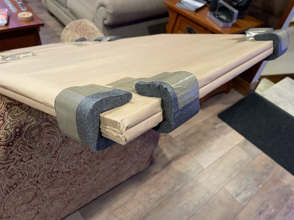
I got home from work and Miss Tami was out mowing. I thought I would use the “me time” to drag the Haunted House cabinet up into the Loft. For a few months now it has sat down below the Loft in the garage area. I’m pretty close to having the main playfield completed and will need a place to put it when done as I complete the other 2 playfields. Seems like the safe place to store it would be the cabinet it would spend the rest of it’s days in. What I thought was going to be a 30 minute job with my Escalara, turned into a 2 hour job instead.
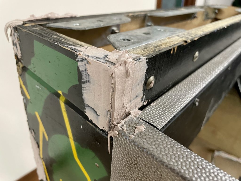
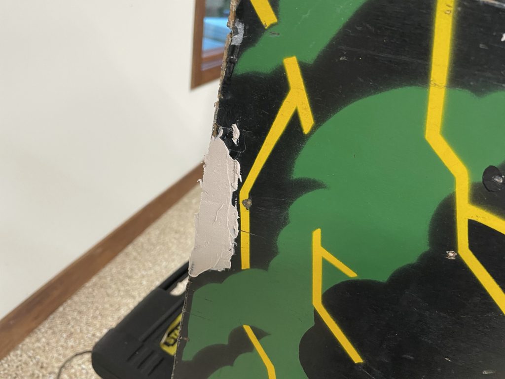
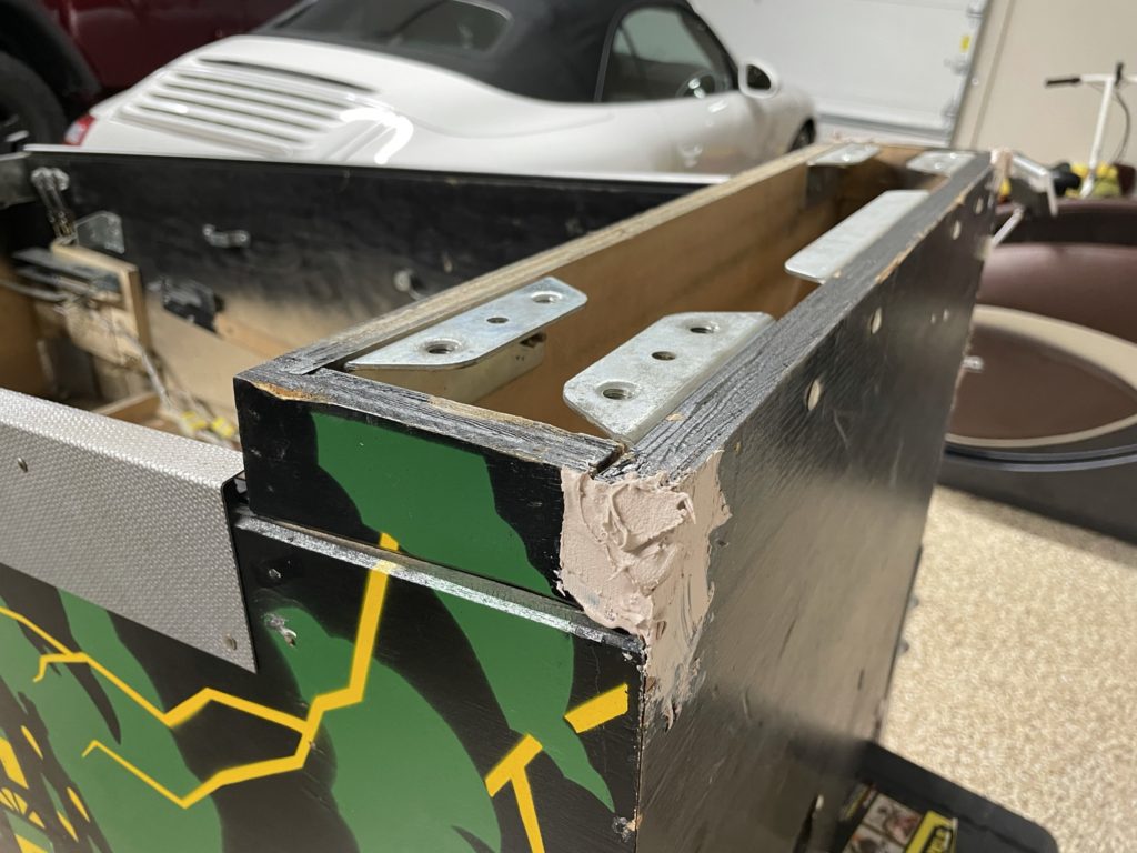
After I unbolted the head and carried it upstairs, I came back down and was reminded how much “love” this cabinet really needed in order to be presentable. There was a large chunk of wood missing from the left side of the neck, there were pieces missing from the left rear edge and the right corner had quarter size chunk of the plywood torn off. The BEST news was that all of this damage was “in the black”. In other words, the black painted part of the Haunted House artwork. None of it carried into the green or yellow (lightning bolts) paint color. That meant I could Bondo, sand and paint those areas pretty quickly. I decided to get the Bondo and sanding done right then and there. I mixed up the Bondo and had it applied in less than 15 mins. I used a little trick I learned when shaping rusty fenders on a car when I was a kid too. If you wait unti right when the Bondo hardens and can no longer be effectively blended or spread – then wait another 3 minutes or so, you can carve the Bondo pretty effectively with a sharp razor knife. This saves many, many minutes of sanding due to being able to remove excess material very quickly. Then, by the time I’m done carving to shape with the knife, the Bondo has set enough that it can be sanded. I had all the repairs done and sanded in an hour. I painted them several days later with a small brush and some satin black paint.
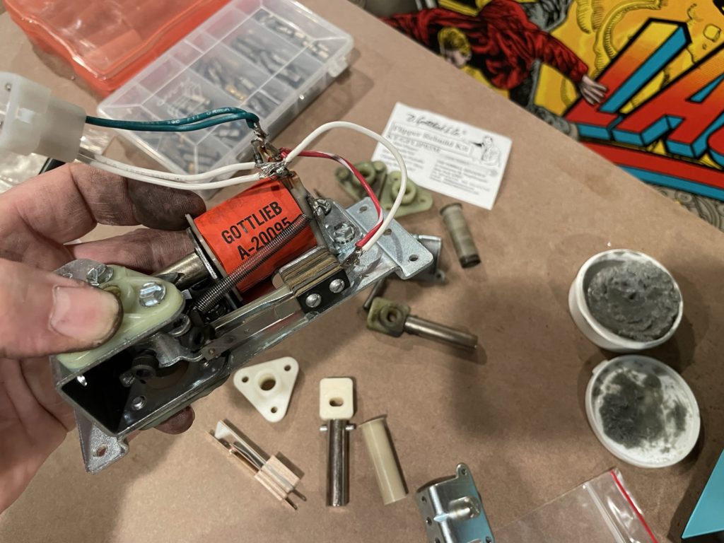
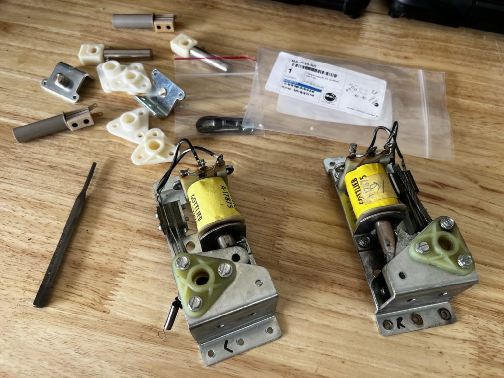
Next up was the process of rebuilding all 4 main PF flipper mechs. I wasn’t sure how much of a challenge this was going to be. After all, it wasnt just the 4 main PF flippers, I had 2 more sets to tackle as this game has 3 playfields. I grabbed the Pinball Resource kits that I had ordered months ago and popped open the packages. The kits include the shaft and link, new flipper shaft bushings for top and bottom (there are 2 in the Gottlieb design unlike Bally/Williams), new return springs, new coil sleeves, switches and coil stops -plus a few extra screws. I pulled one of the flipper mechs from its labeled baggie and quickly dissasembled it. Other than soldering in the new switches and gapping them, the process for putting them together goes quickly. The slowdown comes with the transfer of the old pawl to the new shaft and link. On Gottliebs you need to drive out that roll pin from the pawl and then reseat it. Takes a few minutes but again, it’s straightforward. Use a cracked open vise and a roll pin punch and you have it out in no time.
Mounting the rebuilt flipper can be as simple as lining up the dimples and putting the 6 small screws in that hold it to the base of the playfield. I like to add one more step. With the bottom of the PF facing up on the rotisserie, I will place the flipper mech so that the mounting holes line up with the dimples, then crawl UNDER the PF with a flashlight and check the flipper bushing to ensure it is centered in the PF hole that is cut out to accept the flipper shaft. In all cases the Mirco playfield was either exact or very close (within a millimeter) but even that millimeter can make a difference if the shaft makes contact with the playfield and binds. The method I used was to center it visually from below, then go topside to see how closely the dimples were aligned. I would then find ONE of the dimples that was perfect and set that screw tightly. Then check again under the PF to see if still aligned. If so, back to the top to add a second screw on the opposite side of the mech. With 2 screws in place the mech was rock solid and I could safely add the remaining 4 screws, drilling a new dimple if needed. This process made certain that a dimple that was off by even a tiny bit did not pull the mech off-center as I seated the screw. I got all 4 flippers done in just a few hours total.
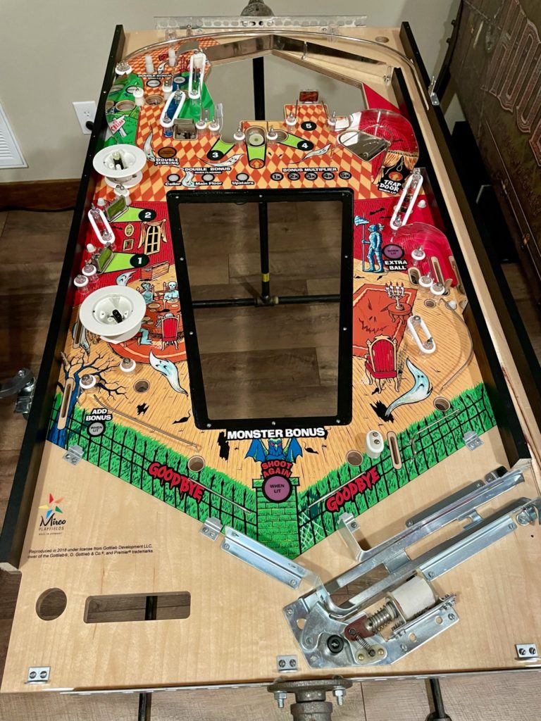
I was in the home stretch of the main playfield now and the only remaining work was to add the numeric display, the pop circuit boards and the large steel hardware that is used to secure, center and support the PF (example: the 2 vertical steel pieces used to support the PF when performing maintenance). In order to get the last bit done, I had to remove the playfield from my rotisserie. The perforated steel supports that hold the PF on each end were in the way of several of the mounting points. I asked Miss Tami to give me a hand and we carefully unscrewed the PF and moved it to a large padded stool that I use for this type of work. Adding back the remaining parts was completed in short order – the bottom of the main playfield was now completed!
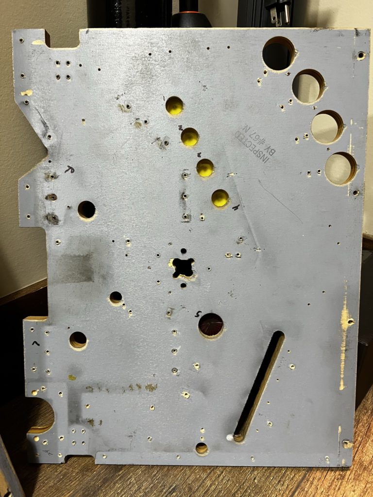
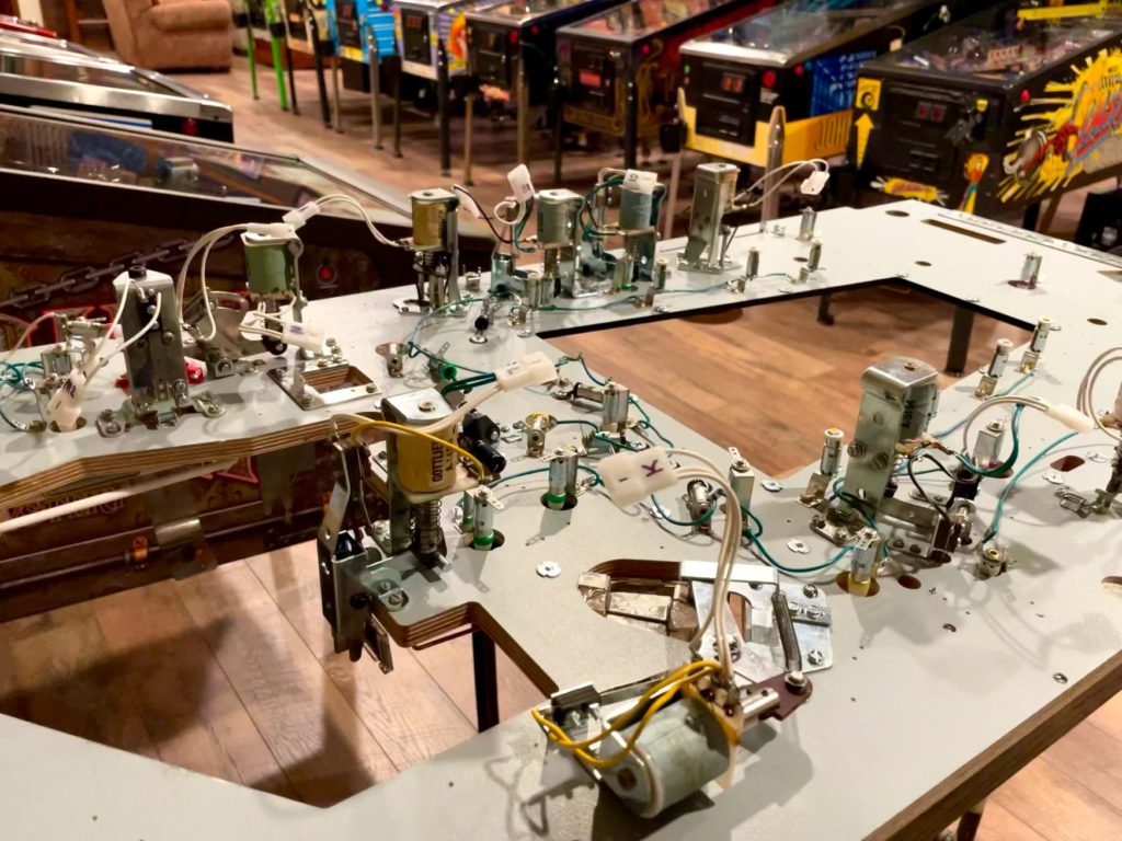
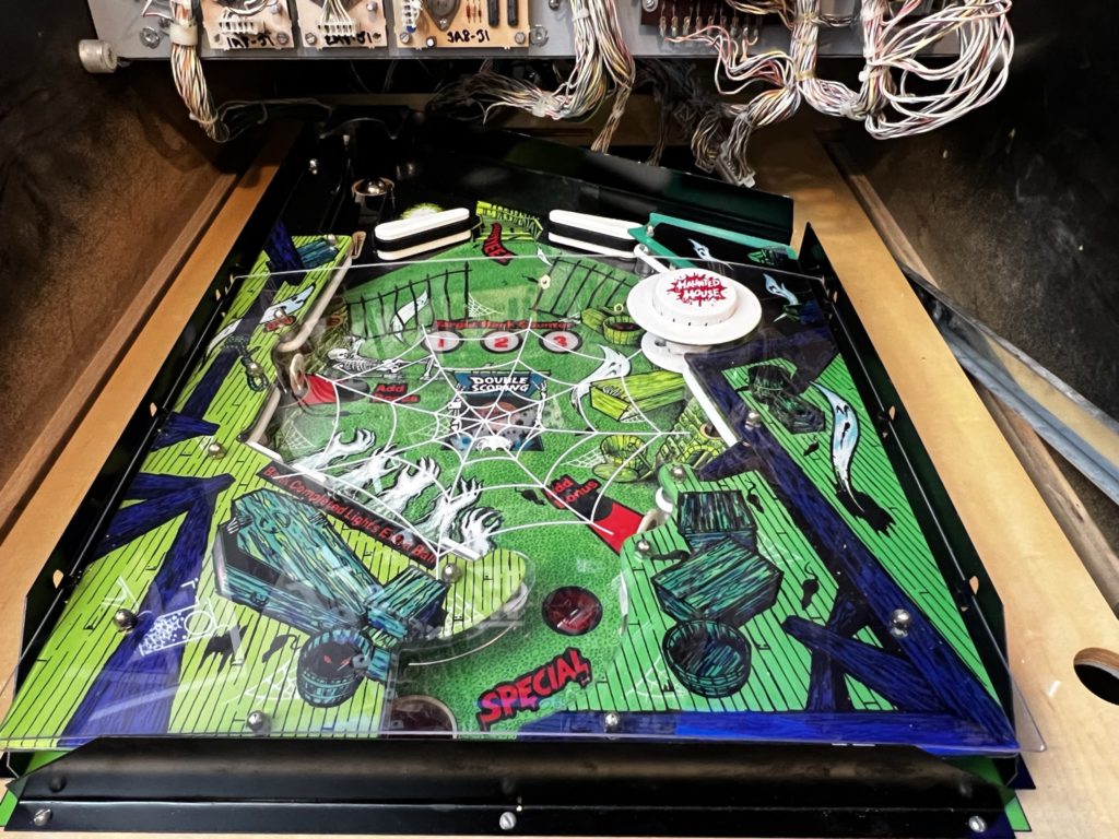
Now my focus was to quickly finish up the 2 remaining playfields. It was only a few hours into the work that I realized that “quickly” was not going to happen. The process is exactly the same no matter what size the playfield! I began with the basement first. Populating the topside was quick and in a few hours I was ready to flip it over and get to work on the underside. I mounted all of the necessary bayonet lamp holders next and substituted some of the original design single tab for newer dual tabs. The plan was the same as the main playfield – eliminate the bare braided wire. Next was to solder in the point to point new wire that would carry current to each lamp. Even something that appeared to be as simple as this takes a bit of thought to ensure that in each case the right tab is connected the right “next tab”. It’s in this situation that the continuity setting on my DMD gets a workout! Once the wiring was complete it was time to prep the old playfield to remove mechs and eventually the underlying harness. The same process I used on the main playfield was used here. I wired every major mech with a molex style disconnect so the mech would never need to be unsoldered or soldered again – simply unplug it and it is no longer connected to the playfield except through screws/hardware. This allows me to unscrew the mech separately from the playfield, move it to my workbench and clean and refresh it as needed. The larger benefit is that the playfield harness is now exposed and more easily moved without all those mechs hanging off of it. In the case of the drop target mech, I left it completely connected. There are 13 individual soldered wires on that mech and it was easier to just move it with the wiring harness
Part 2 of 3: Haunted House Pinball
In the case of the drop target mech, I left it completely connected. There are 13 individual soldered wires on that mech and it was easier to just move it with the wiring harness. I finished up wiring in all the Molex connections and headed downstairs for dinner, not knowing that it would be 4 months before I TOUCHED Haunted House again …
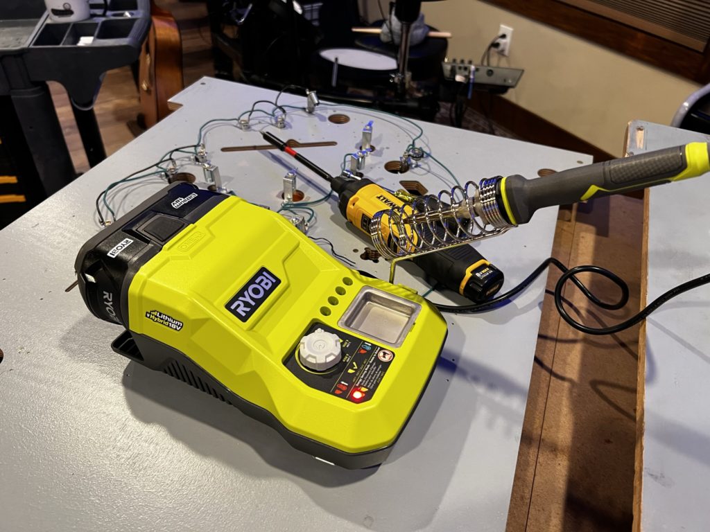
OK, life happens, but it’s almost July and it’s time to get back at it. I set a goal to have the entire game completed by Halloween. The week prior, I saw a FB post about a discount tool site that had a Ryobi cordless soldering stations for $27. I was just curious enough to look it up and read a few (surprisingly positive) reviews. For under $30 I thought, why not try it? I ordered one and when it came time to solder and de-solder the basement playfield, I used it and LOVED it. Heats up to 900 degrees and is very portable. All the work described that involved soldering on the basement playfield was done with this cheap but incredibly effective tool.
I planned to start again on Haunted House the weekend of June 19th but … you guessed it – Father’s Day arrived. Truth be told, I was happy for the pause as work was insanely busy and I needed a day over the weekend to just slow down. My family surprised me with a fun packed day. We started early and jumped in the Jeep to drive to House Mountain for a day hike. House Mountain is just outside of Knoxville and an easy drive. The main part of the trail runs along the mountain ridge/spine and is an easy to walk (sandy and soft). Getting to that trail is far from easy and is covered in rocks with some trails going up near vertical as you ascend. It’s a workout for sure, but the hiker is rewarded with multiple vistas at the top along that ridge trail with views out to several states in the distance. It was a hot day made much cooler by spending 90% of our time hiking under the dense canopy of oak, hickory and tulip poplar trees. Other than getting “lost” (or as I call it “making our own trail”) the trip was uneventful but physically challenging for all. Fathers Day Sunday was over, the work week was ahead and next weekend was all about Haunted House!

The weather leading up to this late June day had been sunny, hot and dry. Today was different. Lot’s of clouds. Still hot and very humid, it was going to be a perfect day to work inside. I headed up into the loft at around 10:30 on a Saturday to begin where I had left off. I had almost completely finished the topside of the basement playfield a few months earlier so I focused my attention on the bottom side. I already had the lamp holders installed and wired in prep to move the mechs and wire harness over. There are probably a hundred ways to complete a playfield swap. YMMV but I saw the smaller/less complex basement playfield as an opportunity to move a bit faster by moving around the playfield in a clockwise fashion pulling mechs (and rehabbing them) as I went. The large mechs were easy (except for the Pops) as they simply required that I “unplug” the Molex connectors that I had soldered on a few month ago. Lamp wires were recorded so that a quick touch of the soldering iron would release the harness from the playfield (remember, the bare wire and the lamp socket would stay behind as I had those installed and waiting on the new playfield). Switches were simply unscrewed with the screws left in the mounting plates and some wide painters tape holding them in place for the transfer.
When I came to the drop targets, I had to slow down and remove the backer plate (4 screws) and replace each drop with a new one. I use a curved angle pick to grab the tiny bale on each spring that holds them into the frame of the mech – it also works well to put the new drops back in. Once I had all the solder points to the lights unsoldered, the only thing left to do was remove the dozen or so screws that hold the harness to the back of the playfield. With that accomplished, I asked my daughter to help me lift the entire harness along with its (still attached) switches and drop target mech. With a “1-2-3” and a smooth motion, we lifted and landed the harness onto it’s new home. Now the real work starts. I won’t go into as much detail as the earlier swap because the process is the same! Align switches before using the provided dimples to drill pilot holes – they are close but not perfect. Gap all switches as you go. Replace all coil sleeves wherever there is a coil. Rebuild the flipper mechs, solder back on all lamps wires and finally, screw the harness back in place. 6 hours later the basement playfield “backside” was complete.
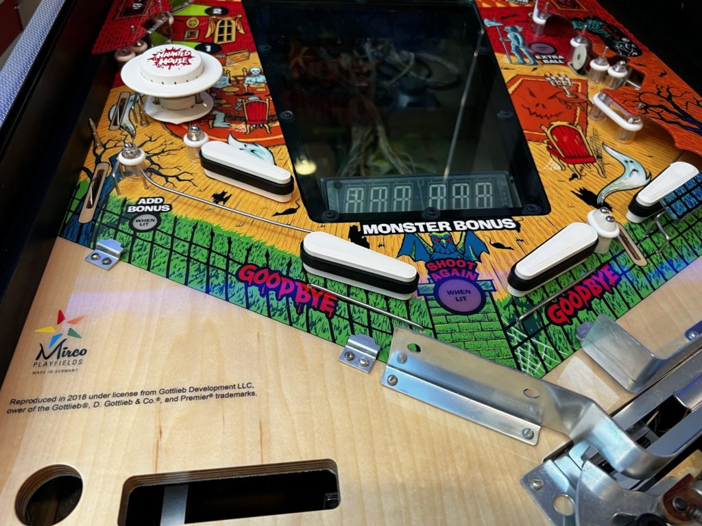
I was putting all my tools away when I noticed the pile of silver metal that had been laying on the storage rack in my tool room. I recalled it was the surrounding metal for the topside area of the basement playfield. I ALSO recalled that I had not installed it yet because the bottom of the playfield needed to be done first AND that Chris Hutchens at HEP had painted his black and I was planning to do the same. Oh heck, I was tired but I grabbed the pile and headed to the pole barn to shoot as few coats of black semi-gloss. That task was completed in short order and I took a break to eat some dinner. In between work sessions I ran out to the pole barn to see if my newly painted basement surround metal had dried. It had, but I was disappointed to see I had missed a few spots. I sprayed it with another light coat and made a mental note to grab it the next evening after work and install it.
After dinner, I told Tami that I was headed upstairs to play a game or two. I had done some tweaking to Ultramans upper playfield and wanted to get a sense of the impact. I played a few games and then thought about how I had not even looked at the attic playfield to get a sense of what was ahead of me. I walked away from Ultraman to pull the attic playfield out of storage. A few minutes later I found myself pulling out the portable work table, the old attic playfield AND my toolcart to do “just a little more work” on Haunted House. 3 hours later …
I de-populated the old playfield topside and re-populated the new one. It’s not a large playfield by any means but my-oh-my, there are a LOT of parts up there! You’ll spend at least an hour pulling and re-installing ball guides as there are close to a DOZEN in that 1 square foot area! Pro-tip … sharpen the guides to a point on your work bench grinder. They will pound in much easier putting less stress on the playfield and/or clear coat. It goes without saying, use a plastic mallet, not a framing hammer as you’ll have much more control on the seating depth per stroke. I also use a piece of 1x wood that is 1/2″ thick as a measure to slide under each guide. The wood gives me an excellent visual of how far I need to go before I’m at the correct depth.
Once the ball guides are in, you can move on to the many star posts that need to be installed. I was pulling them one at a time in order to know for sure which post had a screw top vs acorn nut top. That allowed me to buff each with a dremel as I removed them, then add a fresh clear star post before mounting into the (for sure) correct mounting spot. It is EASY to get confused here as there are around 20 posts so this method worked best for me. I also pulled the rubbers as I went and added a fresh Titan rubber as each new pair of star posts were installed. This saves time “guessing” what size goes where later. I saved the pop bumper and target switches for later so that I could flip the playfield upside down and not have it rock all over the place (rocking on the pop bumper as the high point). With ONLY the star posts installed, they are all level with each other.

It was now Sunday and after returning from church I decided to play some music up in the loft while I worked. I mostly listen to podcasts but was all caught up on my favs. Scrolling through the 10’s of thousands of artists and songs I stopped on an old favorite. The 10,000 Maniacs. The album was “In My Tribe” an old favorite of mine. I listened all the way through and enjoyed the break from podcasts so much I scrolled again looking for more. My next selection was Bruce Cockburn. I was introduced to Bruce by a dear friend in 1977 or maybe 1978. A Canadian singer songwriter that should be 10 times more famous and wealthy than he is. He has had a few “hits” over the years (check out his “If I Had a Rocket Launcher” from his 1984 album “Stealing Fire). He has also produced album after album of thought provoking and sometimes unforgettable music. I have several Christian albums that I call favorites. These are “I heard them once and fell in love for a lifetime” albums. These are albums that I own multiple copies of. I listen to these recordings every year, multiple times per year EVEN as my listening occasions have dwindled – these albums still make the cut. One of those is from Bruce Cockburn titled “Nothing but a Burning Light”. If you like his music, and if a subtle but profound Christian message appeals to you, give it a listen. There have been MANY times I’ve found tears in my eyes as I’ve reflected on the lyrics in these songs – none more profound than the song “Mighty Trucks at Midnight”. A stanza from the lyrics follows- highlights by me:
I believe it’s a sin to try and make things last forever
Everything that exists in time runs out of time some day
Got to let go of the things that keep you tethered
Take your place with grace and then be on your way
Those last 2 lines ALWAYS hit me. Sometimes like a gut punch (feeling guilty as charged) and other times like a simple reminder to keep in perspective what’s important in life. We are not on this earth for long and although Pinball is fun, it’s not what’s really important. Not all of this Cockburn album is full-on serious but it’s all reflective and passionate music from a God connected guy with a talent to articulate that connection in song – check him out if you are so inclined.

Oh, by the way … the OTHER Christian album on my all-time fav list is by none other than Billy Joe Shaver, and is titled “Victory”. For much of his life, Shaver was a hell raiser to say the least. alcohol, drugs and illicit sex were a big part of Shaver’s life – until he met Christ and was changed forever. He wrote and recorded this album after his conversion. It’s titled after his mother’s name – Victory, but clearly the titled plays two roles here. Before he passed away in 2020, Billy Joe Shaver would claim Kris Kristofferson and Willie Nelson as best friends, watch his son die from heroin overdose, marry the same woman 3 times, cut off 2 of his fingers in a sawmill, be inducted into the Nashville Songwriters Hall of Fame and be credited with single handedly starting the “Outlaw Country” movement by writing the songs for Waylon Jennings 1973 “Honky Tonk Heroes” album. He was quite a character. Billy in his own words as he reflected on what drove his conversion to Christianity:
“I was in Nashville with my family, but I was chasing women, doing drugs, smokin’ Camel cigarettes. I was almost dead. I got so I couldn’t even put a sentence together, much less write a song. My family was going all to hell over it…”
https://www.austinchronicle.com/music/1998-08-14/523770/
Back on topic … it was time to move to the backside of the attic playfield. This part went quickly for a few reasons. First, I did not wire-in the Molex quick disconnects. There are only 4 major mechs: Drop target bank, Pop bumper and the 2 flipper mechs. I decided to document the wire colors, photograph each of them and simply de-solder them. This saves a ton of time – like hours. For smaller playfields it’s a great time trade off. Second and more obvious … the playfield is small, simpler and has less solder points. I had the lamp wiring documented, photographed and de-soldered in 15 minutes. With the major mechs un-soldered, they could now be unmounted and set aside for re-build, new sleeves, etc.. The flipper mechs go first and are just 6 screws each (after removing the flipper shaft and bat). The pop bumper coil and frame can come off (3 screws on the frame and two nuts on the pop ring). From here its a matter of unscrewing all switches (no need to de-solder wiring), the wire harness and any remaining mech frames that are going to be moved “en-masse” with the harness transfer (like the drop target bank).
I spent an hour adding new lamp fixtures and pre-wiring the common/connected wiring (bare wire on the old playfield) so it would not need to be done after the harness was moved over (and in the way!). Interesting to note is that the style of fixtures used on the upper/attic playfield are tough to find. These are single tab horizontal mounted bayonets. I used a twin tab substitute as I was going to add insulated point to point wiring so it did not matter. What was cool is that I got to use the same dimples for mounting because even though the lamp fixture was much shorter, I was using flex head LEDs for lamps and their length made up for the difference in the original spec – perfect! The lift and move to the new playfield went just like the other 3 although now on a much smaller scale. Everything lines of nicely, the flipper mechs and pop bumper mech are not in the way (not yet mounted) and there is plenty of room to work with. Because I have pre-wired the lamps (replaced the bare wire with a point to point insulated wire), the only soldering that needs to be done are the controlled lamp power supply lines, the signal control wires (one per lamp) and the 2 pop wires. This was completed quickly with the new Ryobi cordless station set on 900 degrees. I repeated the process described earlier to replace all the drop targets, put new sleeves in all the coils, rebuilt both flippers (I’ve lost track of how many now!) and gapped switches as they were installed.
Part 3 of 3: Haunted House Pinball
Time to wrap this one up. The remainder of the work in front of me seemed never ending but it’s this exact moment in restoring a pinball where I always overestimate the work and time it will take to finish up the game. Case in point- today. I started working a bit on it during a visit from a dear friend – my wife’s uncle Paul. He is not only family but a wonderful guy as well. We love having him around. When Tami and he were busy visiting, I would spend 30 minutes here and there getting one specific part of the work completed. I did not want to spend too much time on the game as his time here was limited and I wanted to catch up with him. This day was Thursday June 30th and by July 2nd, I would be done with the game. Completed. Finished. As I looked at the work ahead of me, I had no idea that finishing in 2 days was possible. Paul left early Friday morning for NY and when I got up, I dug in. What follows is the list of work I completed but I won’t give a running commentary. I’ll save that for the summary at the end.
- Add back all the metal framing to the attic playfield
- Mount the transparent green playfield
- Add mylar to multiple locations
- Add plastics and acorn nuts to all playfields
- Add colored LED bulbs to backbox
- Install the lower (basement) playfield
- Install all topside ball gates (4x on main playfield)
- Loosely install main playfield ramp
- Install the attic playfield onto the main playfield
- Attach ramp to attic playfield
- Install the main playfield in the cabinet
- Connect all harness wiring and plugs
- Install the apron
- Clean and gap the flipper cabinet switches
- Add a new ball
- Turn on the game (1am)
It was midnight. A few hours earlier, I had asked my bride to assist me in lifting out the main playfield while I did a few more things to the basement. i needed her assistance because the main playfield was now VERY heavy with the attic installed AND (as you know) the main PF in Haunted House has wiring right to the very edges on the underside and you have to be careful setting it in place not to disturb the wiring or hit the relays that are exposed near the topmost part of the playfield. Now I had to put it back. I ran downstairs but was too late. She was sound asleep. I was desperate. Should I wake her? Should I try to lift the main playfield into the cabinet alone? Surely the latter was impossible. Surely she would want me to do the former – just wake her up, right? Not a chance. I grabbed the playfield with both hands and walked it over to the front of the game. Moving it was difficult. I had NO IDEA how I would successfully lift it AND even less of an idea how to get it into the cabinet without destroying months of work. I was tired. I should have gone to bed. Instead, I decided to develop a plan and give it a go. I finally hit on the idea that the ONLY way I could safely “rest” the playfield before lowering it in, would be to place it on the props that were installed underneath it for that very purpose.
The challenge remained about how to manage the wiring harness. I had visions of getting the playfield up in the air only to have a harness/plug snag on something and then be caught between a rock and a hard place. In the end, I left the harness hanging down on the underside of the playfield, thinking I could pull it backward around the basement once I got it in there. OK – here’s the plan. The playfield is leaning against the coin door, topside facing me. I grab the playfield about halfway down, push inward on each edge and press it upward to the ceiling. Straight up. Balancing as I press. Once the 2 props clear the lock down area, I gently set it down (still standing vertically) on those props. Now I gently wiggled it back and forth until just one of the props engaged a “tooth” on each edge of the lock down area. I did the same for the other side, then moved along the edge of the cabinet to gently lower it down, inch by inch (all the while watching the props to make sure they didn’t slip. Using this method, I was able to (alone) lift and place the entire main PF and attic PF of a Gottlieb Haunted House. Stupid. (but effective)
I fired the game up around 1am on July 2nd and it came to life! I added some credits and in a few seconds was playing my first game on the virgin playfield. Functionally, the game was operating properly. What a relief. This restoration was complex and required focus and attention to detail. I was so happy to see that overall it had gone well!
That’s not to say I didn’t have a few things to correct. One issue was the weak flippers (2 of them). I had carefully gapped the EOS switches BUT I had not paid attention to ensuring that they were tightly CLOSED when at rest. If they are not closed, then the flippers (if they flip at all) are like slow motion noodles. I re-gapped the offending switched and had VERY strong flippers again.
The basement up-kick acrylic tube needed a bit more space above the VUK mechanism. The wire guide and the plastics to the left of that tube were pushing the acrylic tube to the right and when seating the main playfield were putting unnecessary pressure on the tube. Given the playfield was now installed, I chose to use my Dremel to elongate the plastic mounting holes giving me enough space to now move that plastic more to the left (outside edge of game). I then bent the wire guide just slightly in the same direction. Now when dropping the main playfield into place, the tube fits nicely with no binding.
Installing the transparent green acrylic playfield was not easy. The issue it presented was related to the T-nuts that you will need to pre-install in the playfield. Once they are hammered in, the location for the screw is locked in as well. I suppose it’s an impossible ask for the makers to align the countersink perfectly to the T-nut location. They were “close” but not close enough. Could I get the machine screws in? Yes, that was easy – the holes were very close to perfect alignment and they were a larger diameter than the screw providing some flex in the placement. The problem is the countersink. The countersink pattern, for the most part was not aligned. This allowed me to get the screw into the T-nut under the playfield but not be able to tight it down because it left the screw head proud to the playfield (and easily hitting/deflecting the ball). I marked the direction that the countersink would need to be biased on a piece of paper and then removed the entire green acrylic playfield and took it outside. I used my Dremel to create a wider arc in the countersink in the direction I had previously marked. The process of removing that small amount of material worked and I was able to install the acrylic playfield and keep the screws flush.
Another small obstacle was the main playfield ramp. It connected/met the attic playfield just fine, but it was lower than the attic at the transition point. Low enough that repeated ball strikes would quickly damage the leading edge of the attic playfield plywood. I cut a piece of target foam the width of the mounting channel that sits at the edge of the attic and pushed it into place with a thin file. When I reattached the ramp, it was perfectly level – note that this is also one of the areas I added a small piece of mylar to. I added a 3/4 sheet of mylar on the entire basement playfield. It was easy to see the worn areas on the old one and given the area that was impacted was large, I just covered the entire lower 3/4 of the basement. I added 2 pieces of mylar on the main – one at the basement kickout and one at the saucer. Both pieces are about 1.5″ wide by 4″ long. The attic playfield got a piece at the ramp (as mentioned above) and a piece where the ball pops onto the left side out of the VUK.
Adding the plastics was a pain. Acorn nuts suck. Big time. My method is to use my 5/16″ nut driver and cram a balled up wad of painters tape into the tip. I’ll add one small folded up piece of tape at a time until the acorn nut is no longer able to drop fully into the nut driver head. This gives you the ability to apply downward pressure to the nut as you turn it, thus allowing faster installs. Notice I said faster not better – they still suck vs a nylock nut! Of note also is that I bought the plastic protector for the long left plastic in the basement – the one that is always broken. It’s cheap and is available from Marco.
One other “tweak” I had to make was to orient the upkicker acrylic tube that comes from the basement. I originally had it so the “point” end was facing the player. It won’t work because when installed that tube comes very close to the basement playfield and in that orientation, will hit the ball. In my case if was so close it simply stopped the ball from entering the VUK mech. I tilted the playfield up, loosened the aluminum band holding the tube and rotated it so the point of the tube was pointing to the left cabinet side, allowing lots of room for the ball to now enter the VUK. Problem solved!
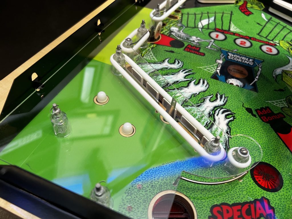
Playing Haunted House in this freshly restored form is a reminder of what it must have been like to first see one placed on route in the early 80’s. It’s a stunning game visually and blazing fast gameplay at times (yes, molasses slow at others). It’s a simple game but presents challenging shots as well. Even getting the ramp shot from the left flipper is no gimme. The basement is a fun challenge and presents multiple targets not just a one and done. Knocking down drop targets appears to be a task that is vanishing from modern pins but in Haunted House you get 2 banks of them. The attic drops are cool because they are visible, and quite easy. The basement is a little tougher for a couple of reasons, not the least of which is they are hard to see.
Playing it now also brings a little anxiety. I’ve spent countless hours (200+) and untold amounts of thinking and planning to pull this off. I play with a little voice in my head telling me that I’m about to break something! Obviously this is true … if you plan ANY pinball long enough, something will break. Fortunately this particular example of Haunted House is protected better than most. It has freshly rebuilt flippers, a mylar protected playfield and hundreds of new parts. It’s been a functioning and playable machine for the last 40 years as of this June. I’m betting on another 40 more!
Haunted House Spend: Total $4,000
- $2,000 base game
- $1,100 3 pieces Mirco Playfield’s
- $275 Pinball Resource parts
- $82 Marco (lamp sockets)
- $75 Pinball Life (lamp sockets)
- $75 Pinball Life (PF rails)
- $200 plastics
- $50 apron decals
- $150 LEDs
Haunted House Wiring & Notes:
Main playfield controlled lamp & GI wiring colors:
- 1 red green and green gray
- 2 purple black 2x and red gray
- 3 purple black 2x and red gree
- 4 black 2x and purple gray 2x (GI)
- 5 black 2x and purple gray 2x (GI)
- 6 bare and orange gree
- 7 bare and orange black
- 8 bare and brown purple
- 9 bare and brown blue
- 10 bare and purple green
- 11 bare and purple black
- 12 bare and brown purple
- 13 bare and purple red
- 14 purple black 2x, bare and purple orange
- 15 bare and green
- 16 bare and purple gray
- 17 bare and yellow green
- 18 bare and red orange
- 19 bare and green blue
- 20 bare and purple orange
- 21 bare and green black
- 22 bare and brown green
- 23 Special thru PF
- 23 black 3x and purple gray 2x and white single wire out to 23B AND single wire out to 24 lamp
- 23B bare and white wire from 23
- 24 black 3x and purple gray 2x and receives a single white wire from 23 to the purple gray connection
- 25 bare and purple gray 2x (GI)
- 26 purple black 2x and yellow green
- 27 black 2x and purple gray 2x (GI)
28 volt lighting circuit:
- 28 volt High voltage GI LEFT
- Bare is fed by green 2x on lowest lamp on flipper end
- Signal is all purple gray 2x (at each lamp)
- 28 volt High voltage GI RIGHT
- Bare is fed by green 2x on second to lowest light on flipper end
- Signal is all purple gray 2x (at each lamp)
Main PF Controlled Lamps LED colors – Bayonet flex heads:
- 1 orange
- 1 green
- 2 yellow
- 8 Sunlight
- Bayonet 44s:
- 9 Sunlight
- 4 green
- 2 red
Backbox LEDs:
56 pieces plus 1 flasher #455
Basement playfield controlled lamps wiring:
- 1 green 2x, black common
- 2 none (new wiring – was purple and common)
- 3 none (new wiring – was white and common)
- 4 green 2x to black new wire tab
- 5 none (new wiring – was bare wire and common)
- 6 green 2x to black new wire tab
- 7 none (new wiring – was red and common)
- 8 green to open tab, purple pop bumper to common, blue/red pop bumper to open tab
- 9 blue orange 2x and common
- 10 green orange 2x and common
- 11 yellow orange and common
- 12 green orange and purple black on common (+ common)
- 13 orange and common
- 14 blue orange and common
- 15 purple and common
Attic playfield controlled lamps wiring:
- 1 tab purple/blue
- 2 tab purple/green
- 3 tab yellow/purple and heavy purple blue to common
- 4 tab purple stripe 2x and green/purple pop bumper plus common black stripe 2x AND green/light green pop bumper
- 5 black stripe and common
Upper playfield flipper wiring:
Right Flipper:
Green to outside lug, non banded diode
Black/yellow stripe to outside lug, banded side of diode
Left Flipper:
Green 2x to non banded side diode
Black/green stripe to outside lug, banded side diode
Star post counts:
- 22 clear posts on upper
- 19 clear posts on lower
- 26 clear posts on main (2 pieces are taller)