Handsome Harlem
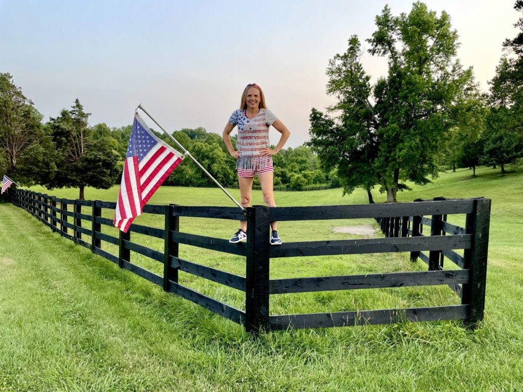
Where do I start with this one? Wow, just …. wow! This restore has been the most (by a mile) detailed and extensive I’ve ever undertaken. I guess it makes sense to start with the Globetrotters themselves. Like most baby-boomers, I knew who they were from a very young age. I grew up with them. I grew up watching them on Saturday cartoons. I got to see them live later as an adult. Their red, white and blue colors are as Americana as it gets. Apple Pie, Hot Dogs, Ice Cream, the 4th of July and yes, throw the Harlem Globetrotters in there too. U-S of A all the way.
When my daughter was younger we took her to see them right here in Knoxville and Meadowlark was with them. We had a great time and I enjoyed it just as much as she did but the special moment came at the end when Meadowlark himself signed a “kid sized” basketball for her. He was exceedingly kind. There have only been 12 pinball machines in history to exceed 15,000 units in sales. Harlem sold 14,550 units total – easily putting it in the top 20 best selling of all time. There’s a reason. It’s fun to play.
So how did a bit of nostalgia get me interested in owning this machine? After all, I already had a room full of them. You can blame it on RD or, as he is know on Pinside as “Rotor Dave”. The Rotor comes from his old racing days (Mazda engines) and he lives in New Zealand with his beautiful family. In fact his daughter Dani is one of the top ranked female player in the world. I got to see her in action when Dave and his family came to visit here in East TN and we played a 4 player on my buddy Darin’s WOZ. I’ll sum it up. She crushed us. Like really bad. RD also just happens to have one of the largest pinball collections in the world. Set up in his home, ready to play – he has in excess of 100 machines! He’s a music fan, an entrepreneur, a competitive pinball player, world traveler and all around renaissance man. Dave Peck was kind enough to share his building plans for his home and gameroom in New Zealand and I used many of his ideas from those plans in building my pinball loft. So what’s Dave got to do with the Globetrotters? Did he used to play with them too? No … but he did buy a beat up Evel Knievel pinball. He did do a fabulous restoration on it. When he posted on Pinside the results I was blown away. It looked like something I could do and wouldn’t you know it – Globetrotters is the same era, the same manufacturer and just about the exact same level of complexity to tackle. I went on Pinside, told Dave his work was fantastic and 30 DAYS LATER I posted again to let him know it had inspired me to do the same but with a Harlem Globetrotter instead of the EK title.
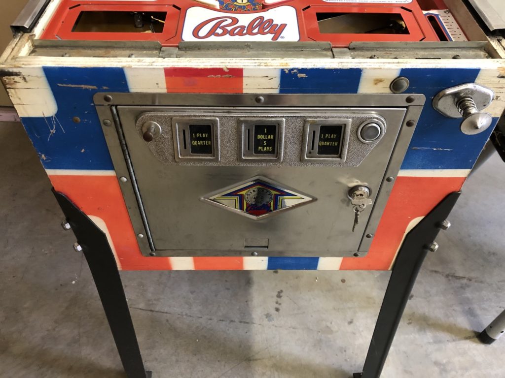
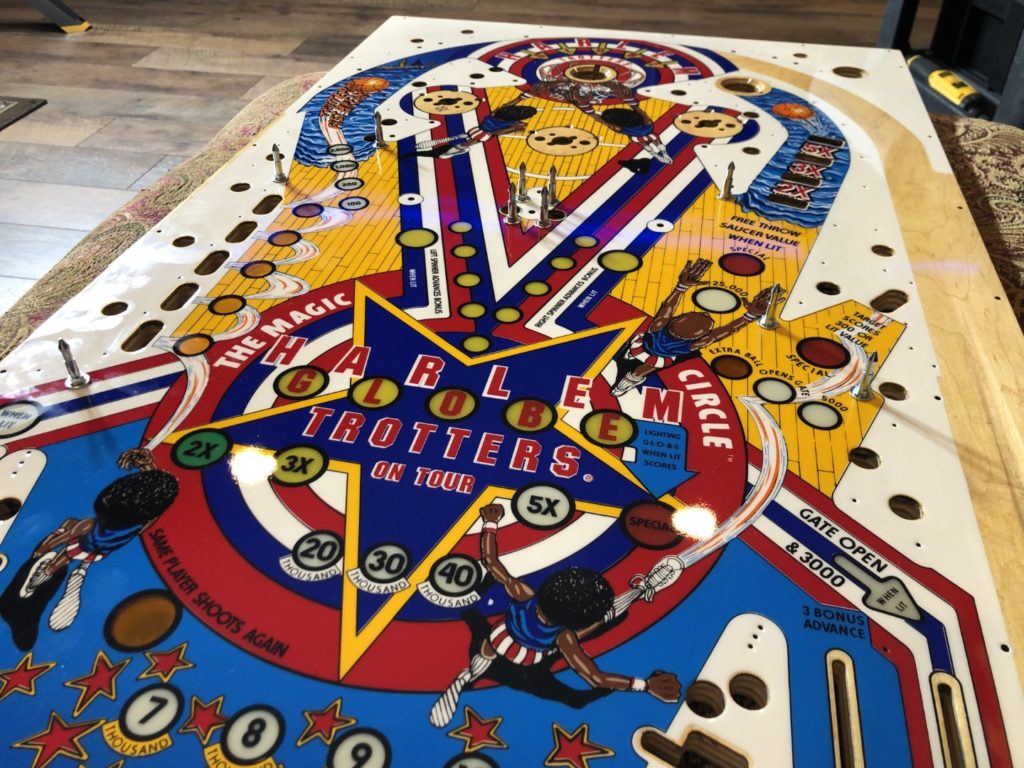
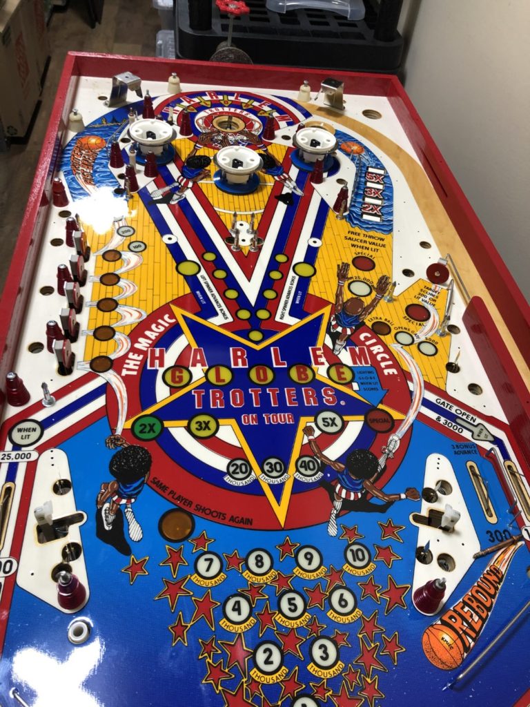
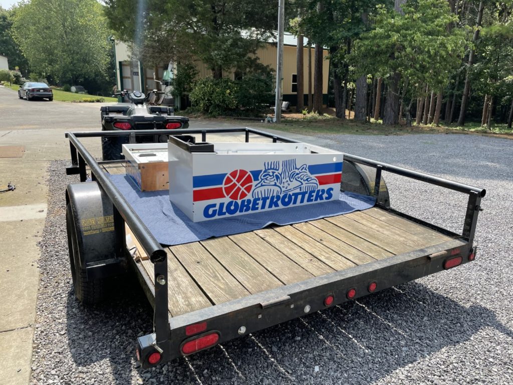
So I started my search for a Harlem Globetrotters and it did not take long to find one. Convenient for me – it was nearby. Not more than 45 minutes away there is a friend that deals in and repairs used pins. He especially talented at taking non-working ones and resurrecting them to working order. In the meantime, I mentioned to my wife that there was a Harlem Globetrotters pinball and because of our love for the team and our little bit of history, that we should keep an eye out for one. She seemed mildly interested which in more interest than she typically shows for pinball so I took that as a “start looking harder” moment. It wasn’t too much later that I saw a FB ad that my “pinball resurrection” friend had placed for a Harlem Globetrotters and I messaged him right away. We arranged a time for me to go look at it and away I went. The game played well and I could see why folks enjoyed this era game. It was deceptively simple and quite challenging to do well on. It also had the Sweet Georgia Brown theme tune built into the very rudimentary sound system that was available to pinball designers in 1979. The playfield was worn but I cared more about the overall “bones” of the game. Cabinet sound? Check. Backbox square, no splits? Check. Topside components all there? Check. Coin door in decent shape? OK, not great but OK. Game plays correctly? Check. I could overlook the cabinet scratches, the missing paint, the worn playfield and the flaking backglass. All of that would be replaced during the restoration process.
I purchased the game and hauled it home, knowing it would be months before I started the restore. In between that time I set it up in the pole barn for some test play and to get a better idea of what parts would be needed. It got played quite a bit at our annual barn party at the ranch and the guests all commented on the game even if they didn’t play it – people universally like the Harlem Globetrotters. After the party, the game was unplugged and moved to an out of the way spot in the pole barn. January passed and in February I began to assess and order the parts I would eventually need for the restore. The cosmetics were rough but the bones were good. Then, out of nowhere, COVID-19 hit.
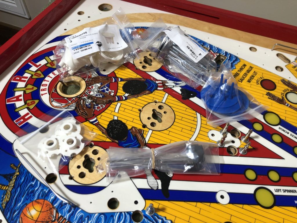
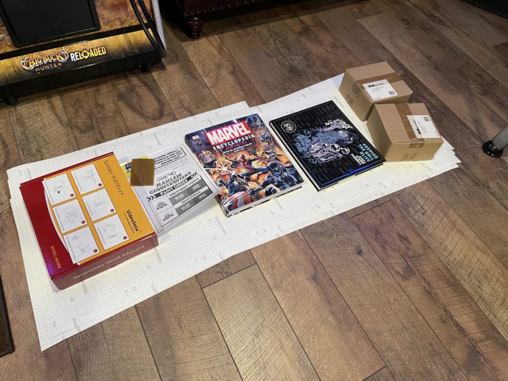
I got insanely busy at work (busier than at any other time – we are an essential business) and even though I was working from home, I had ZERO minutes to work on the game. The parts were sitting upstairs in the Loft but it didn’t matter. Many nights I was still working at 10 or 11pm and the only thing I wanted to do when done was get some sleep. After several months of high intensity, the number of cases nationally started to level off and states began to “open up”. I was one of a handful of folks who returned to our offices (albeit with masks and a whole slew of new processes) and for the first time in several months – I had some time off. My evenings were back and even some weekends. I got to know my family again and dove head first into getting Harlem done ASAP. Here is what I had ordered:
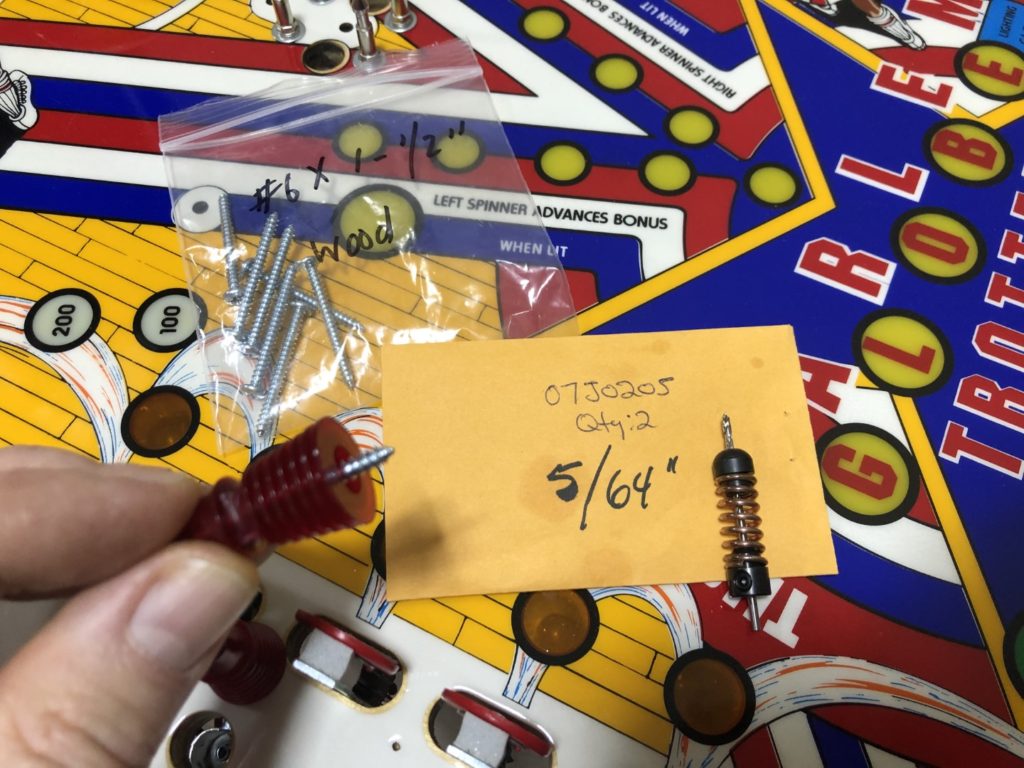
- Bags of new hex head mech and switch screws
- New pop spoon switches
- New pop bumper mechs
- New coil wraps (printed “Bally green”)
- New back glass (CPR)
- New back glass frame kit
- New playfield (CPR)
- New side rails (chrome)
- New stand up targets
- New rubbers
- New mini posts
- New bulb holders (100% replaced)
- New “Reese” rails
- New plastic set
- New legs (chrome)
- New coin door bezel (chromed)
- New vent screen (chromed)
- New speaker (custom painted)
- New flipper bats
- New flipper buttons
- New flipper button housings
- New flipper cabinet switches
- New coin door skin
- New backbox lock
- New service/operator cards (65lb stock)
- New ground braid
- New bulbs
- New switch resistors/diodes
- New apron decals
- New spinner decals
- New Pinball Pimps stencil kit
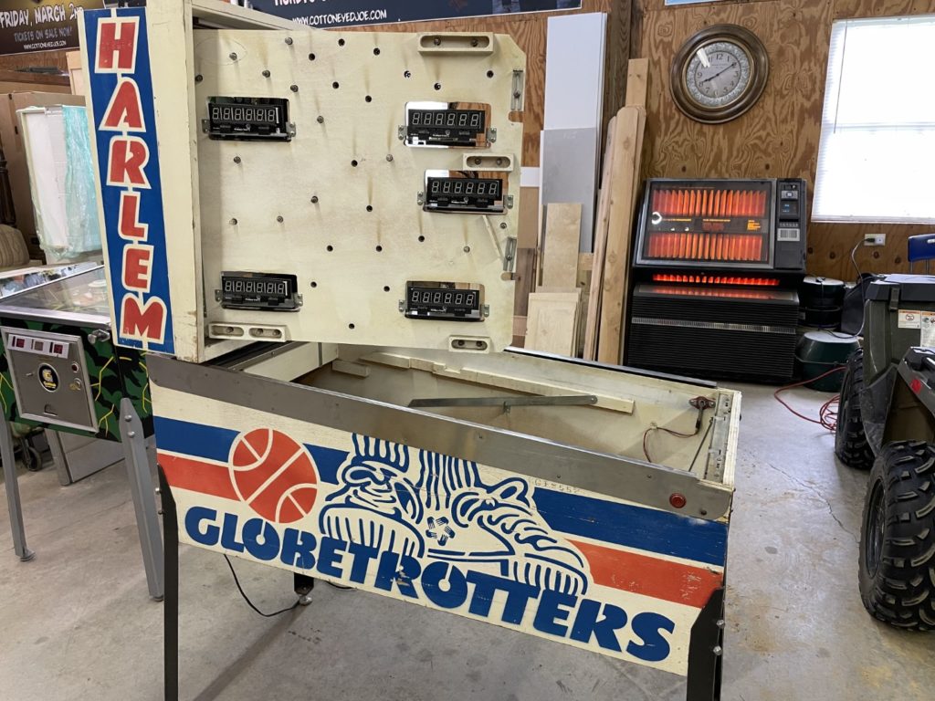
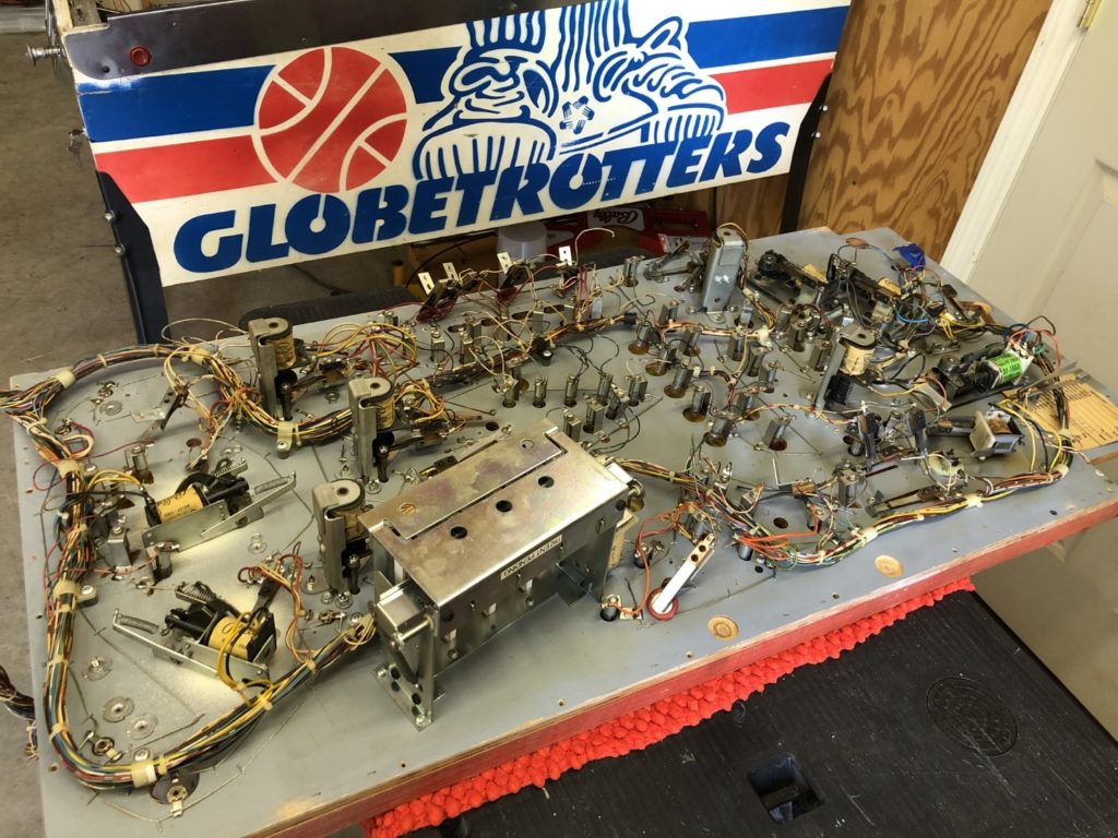
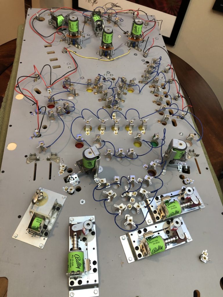
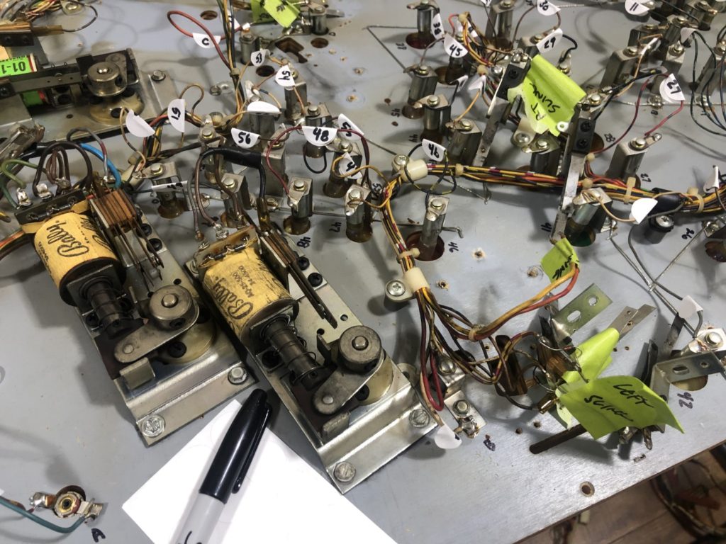
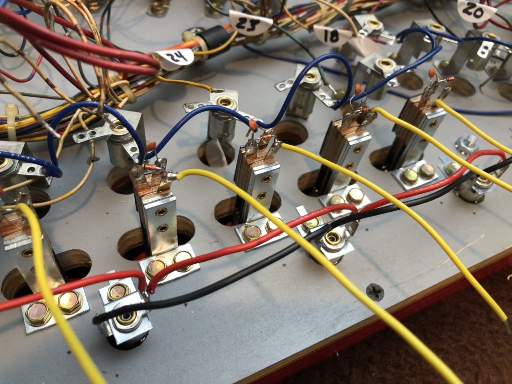
On a rainy Saturday I walked over the pole barn and pulled the glass from Harlem. In about 2 hours I had the top cleaned off and had taken hundreds of pictures along the way. I pulled all the mechs apart, took off the solenoids and dropped all the metal parts into the tumbler for polishing.
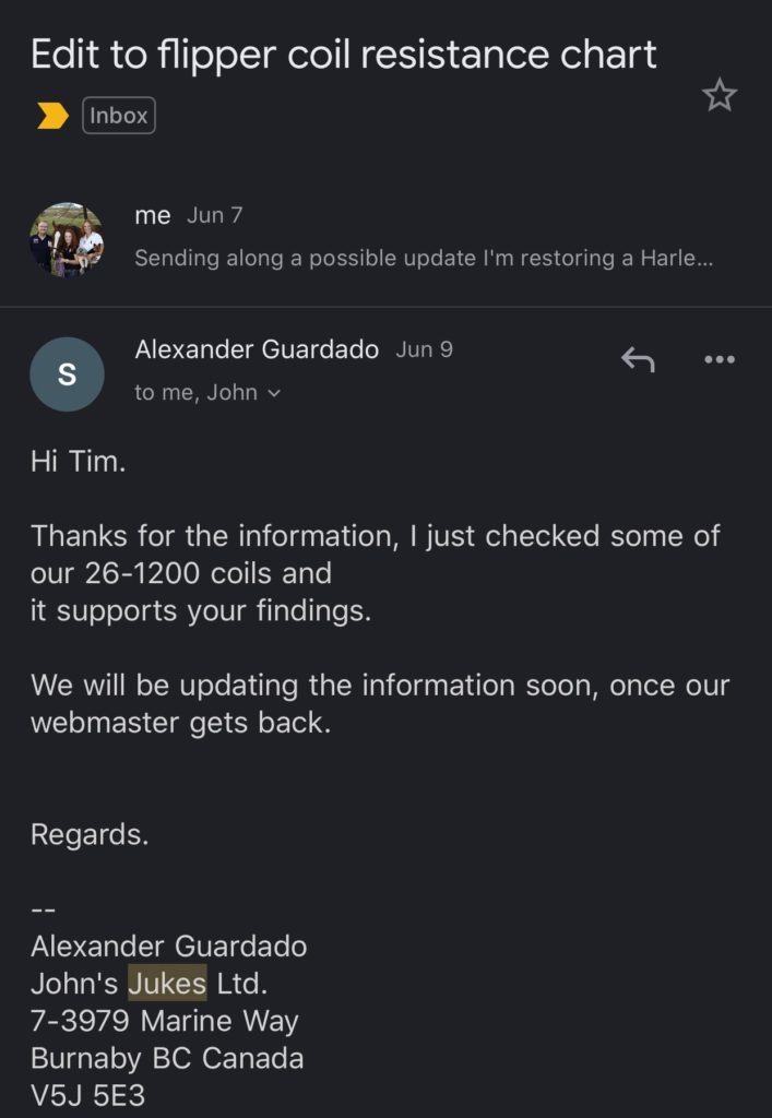
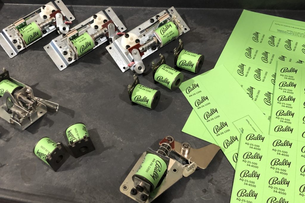
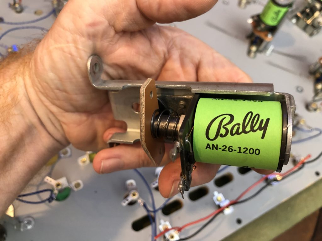
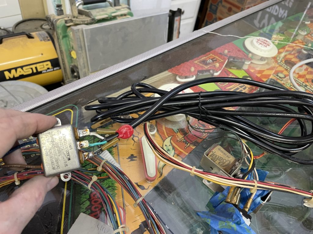
I used my new sonic cleaner to clean all the coils and once out of the Simple Green sonic bath, I pulled the (now gummy and faded) labels off the coils. That was a mistake. How the heck would I know which coil went where? Aha- DMM to the rescue! I measured the resistance of each and compared it to John’s Jukes coil charts BUT … there was a problem. My AN 26-1200 coils (slings, pops out hole) were measuring 10.7 to 10.9 ohms and John’s chart said they should be 12.5. I measured again and again – came up the same for me … averaging about 10.8 ohms. Then I did some deep research on the internet and found that at least one other source was getting the same resistance numbers I was. I shot an email off to John and they quickly got back to me that … yes, the 10.8 ohm number WAS correct and they would be editing their charts to reflect the change. They tested some coils they had on hand to confirm the same measurements that I had taken.
With that settled, I now “knew” which coils went where and could begin the process of re-wrapping them for later installation. Wrapping the coils with fresh wrappers should be easy – right? Not so much. First, even though Planetary Pinball sells wrapper “kits” they don’t have one for Harlem. Secondly, for whatever reason, I tend to fall in love with the most complex solution to a problem. Ken Layton had posted on Pinside that had printed Bally coil wrappers in the most beautiful green I had ever seen. He was even so kind as to share the specific color and brand of the paper he used. It was Neenah Creative Collection, #98710 in Avocado green. Awesome, right? Well it would have been if that paper was still being manufactured, if it was still in stock within a hundred miles of my house, if the folks that DID still have it in stock would ship me some BUT … sadly, none of that was true. I found some a little over a hundred miles from my house and begged the store (that also had a “pack and ship” service IN the same store) to ship it to me – I did not care the cost. They wouldn’t. So I paid my daughter to drive and pick it up. Such is the obsessive nature of this hobby that I had to have that exact green, for coil wrappers that almost NO ONE would ever see.
Next I moved onto finding out how to print the coil wrappers with the Bally logo, coil number and at the right scale to fit each coil. This part was assisted greatly by Pinballrebel.com/pinball/cards. It’s here that you can find and download instruction cards, cabinet body cards, and coil wrapper files. It’s a one stop shop for anyone that wants to restore a game to “better than new” condition. Download the file, print it out in black ink and each sheet will have more than enough wrappers on it to do every “like” coil on the game. Some use double faced tape to attach, but I just used transparent tape and put the seam at the bottom. The game looks 1,000% better with the new wrappers!
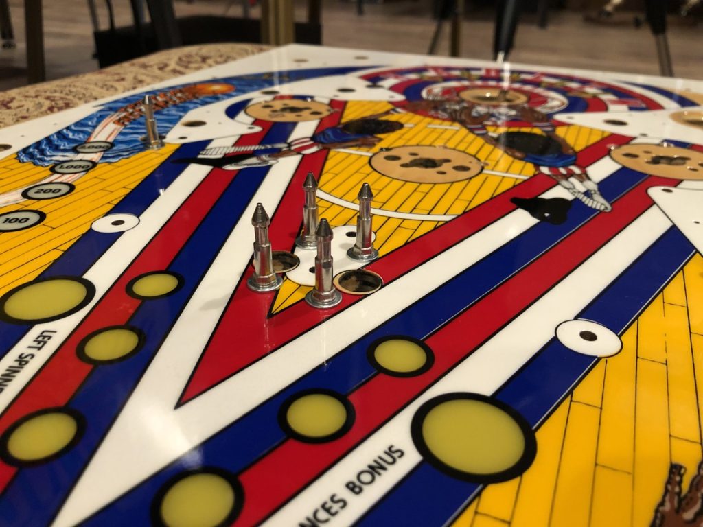
Time to do all the hammering on the topside first.
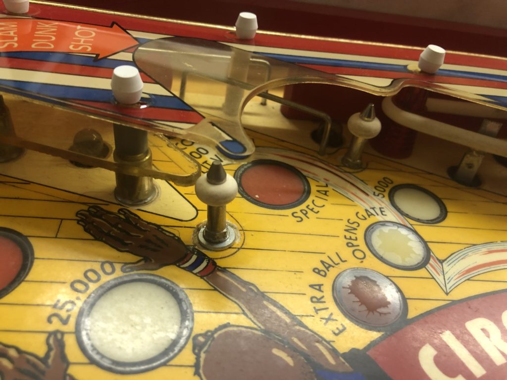
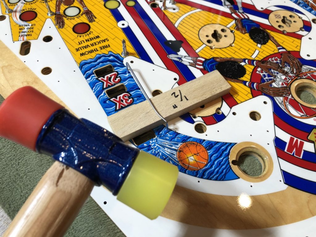
Busy, busy now … hammering in pop nails. Clearing away clear coat. Adding pop parts and seating the body. The bodies did not fit and I had to Dremel and file a bit. I even put a tiny scratch in the playfield (under the pop bumper thank goodness) while trying to file off a bit of the pop bumper body to make it fit. The wire leads for pop bulb holder were also a very tight fit. Next I was on to hammering in the ball guides. I used a block of wood for measure and to ensure they were seated to the proper depth. Pre-drill the back side of the guide holes and watch guide as it exits the back – splintering may occur! I added the posts on the top side just to get a feel for what it would take to carefully remove the clear, seal it with premium CA glue (super glue) and then carefully tighten down. I abandoned the glue after the second hole as it made a mess around one of the holes.
All 10 or so mini posts were added without incident and I gained confidence that I could handle re-populating the topside when finished with the bottom. I knew it would be a little more challenging because some of the items on the top would require all the prep work that the mini posts had required AND they would need to be “pre-drilled” as well (think wood screw based posts that support plastics and star posts)
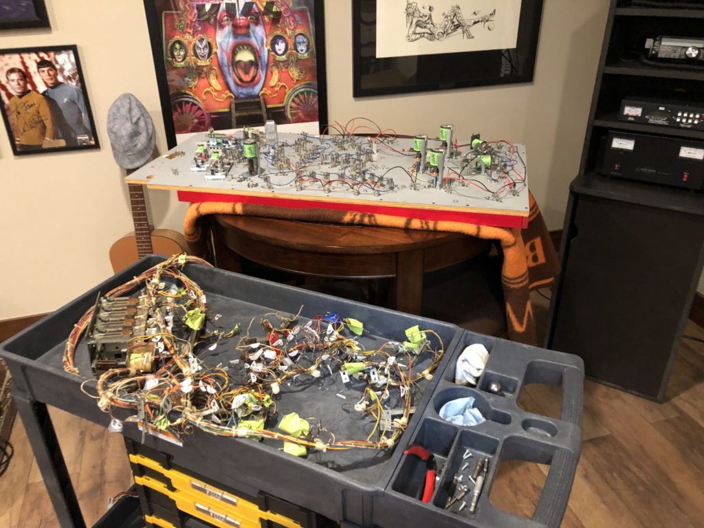
By now I was out of the pole barn and had hauled both the old and new playfields up into the Loft where the temperature and climate was about 100% nicer than the tropical pole barn. I set the old playfield up on my rotisserie and the new one lay on a blanket on my gaming table in the corner of the Loft. The first thing I noticed was it was too dark to work effectively – like way too dark. I went on Amazon and after a few nights of research ordered a new freestanding LED work light. Best decision ever. It’s adjustable for aiming, it’s pretty lightweight, it folds up in a very compact form and it was only around $100 – oh … and it’s bright! My storage closet in the Loft doubles as a place to do minor repairs and now that I was into MAJOR RESTO I noticed that this space was also quite dark. Time for another visit to Amazon. This was simple and cheap purchase. It’s a high output LED light that screws into the bulb fixture of a recessed can light. Cheap, bright, fast and effective … and ugly as sin but I didn’t need beauty, I needed functionality.
Got my new Reese rails in and added those to the playfield. Had to buy some new rail screws because the original rails were stapled in with just a few screws holding them. It’s not like they were going to go anywhere – the staples were a huge struggle to pull out and I had to use a combination of the levering the rail against the playfield and a large screwdriver to essentially “pry” the rails away from the playfield.
Tonight I ran through the entire inventory of bulb holders for inserts. I cataloged each and every wire and color code, then wrote a corresponding number on the old playfield
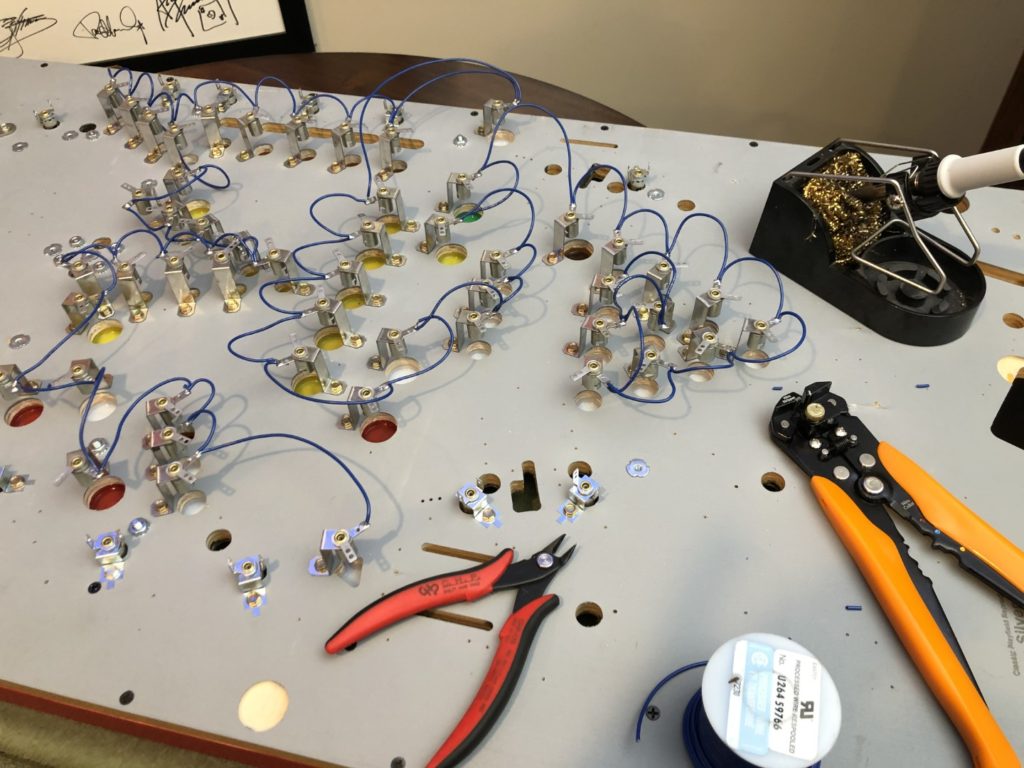
Today I soldered in the entire 5 volt point to point for all the “below-the-playfield” insert bulbs. Took me 2 hours start to finish. You must have a good quality stripper tool. It saved hours of stripping time. Just locate the wire where you want it stripped and squeeze the handle – boom, bare wire. The wire I used was 18 gauge for both the GI and the Controlled Lamps circuits. If you’ve followed some of HEPs restorations, you know that there are several ways to rewire a Bally controlled lighting matrix. You can use the original method of stapling down a 5 volt “bare wire”. Pretty simple because you use the old playfield to just follow along with the old pattern. The move the old harness to the new playfield and connect the other wire. Simple but also requires specialized wire and a good stapler and some planning. When completed this way, you’ll need to add a solder blob to each spot where the 5 volt braid touches the bulb holder – so in essence, you’re stapling down a wire, then soldering it as well. The other potential downside is removing bulb holders later on to replace a bulb – not so easy. Another way is to use what are called “solder tabs”. These look like a washer that has an extended “leg” for you to solder on. The advantage here is that you can still staple down the bare wire, but now you will be soldering that braided wire to the tab and not the bulb housing – thus giving you the ability to change bulbs very easily later on.
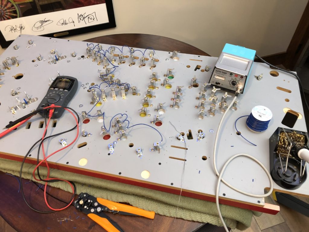
The third way (the method I used) was one I copied from Chris Hutchins at HEP. This simply involves ordering new lamp holders with 2 solder points and “lifting” the normal braided wire off the bottom of the playfield and changing it out for a normal insulated/stranded wire. Solder those wires all to the same bulb holder tab and then solder on the control wires from the wire harness to the other tab. In my case I used blue as my 5 volt wire. The tabs on the bulbs holders have holes in them large enough to accommodate the wire itself when it is stripped and threaded through. In many cases I was able to cut a length of wire long enough to daisy chain 5 or 6 lamps with a contiguous piece of wire. I used the strippers to split and “slide back” the insulation at each bulb holder solder point, then threaded the entire piece of wire from the starting bulb to the end. This was not a fast process but it worked and it saved a bunch of soldering because the wire slipped through the bulb lug required just a single shot of solder and it was complete – no fumbling with cut pieces of wire. This was especially helpful when you are working alone – like most of us do, most of the time.
I was surprised at how quickly the controlled lamps were completed and excited to then move on to tackle the GI wiring. First, I needed to choose a color combo and ended up using black and red coded wires. Gauge was the same as the controlled lamps (18 gauge) and the wire came from the same supplier. Oddly enough, I had more trouble with the GI than the other lamps and there are FAR fewer of them.
Most of the issue was simply me not understanding how the GI worked. The GI has multiple “feed points” from the wiring harness. Some short runs will have a positive feed from one end and just 12 inches away be fed by the negative. I’m guessing that clarity of design was not a real concern but that “wasting wire” was – so I they could just grab a ground nearby rather than run another wire – they did it. Just like I did on the controlled lamps, I was super careful that I was watching what lug I was soldering the ground vs the hot and keeping it very consistent.
That process was working just fine UNTIL I was checking the old playfield for reference and noticed that on one of the lamp holders, the wires were “flipped”. Huh? Yes – the ground appeared to be soldered to the lug that on the prior lamp (and it was the lamp feeding it) was opposite! How could this be? I feverishly began to check all my work vs the old playfield. Sure enough 4 or 5 others were “flipped”. I spent another half hour “correcting” each of them until I came to the conclusion that I did not have a clue what I was doing. Confused, I jumped on Pinside to find out what was what. Got it. The GI is AC not DC, and polarity does not matter. No wonder the Bally guys “appeared” to just slap those wires on the lamp holders seemingly at random – it just doesn’t matter. Ugh. Now I know and the next one gets easier. Another step I took to make the connection of the harness easier was to solder in a short piece of wire when the wire harness was expected to make a connection to a lamp lug. That way I would not disturb the existing solder point on the lamp lug and could simply slip a short piece of shrink tube over that wire and solder my harness to the short wire. Once soldered on, just hit the shrink tube with the heat gun and be done.

I began to add back all of the large solenoid based mechanisms. The new flipper mechs from PBL, the sling mechs, the 2 upper saucer mechs, the lower ball diverter mech and finally, the pops. There were lots of intricacies and things to learn along the way. Changing out the spoons on the pop switches was no easy task. The new spoons had mounting holes (for the switch screw sleeves) that were about a millimeter too small. Getting the bottom “nut plate” back on requires patience.
Switching the sling arms to the more modern “2 piece” style brought it’s own set of challenges. The mounting hinge has new drill points, the hinge requires a washer/spacer. The fiberboard swivels were just a tad too tight to slip onto the mounting post on the sling arm. Thank goodness for the Dremel. Mounting the pops was actually one of the easiest parts – after all the pop nails are already in place, just drop the mech over the screws and put the 3 nylok nuts on, line up the pop ring with the yoke and add 2 more nyloks and you’re done!
The saucers presented a small challenge of “where to locate them” – not that the large holes in the upper part of the playfield didn’t give away the placement but, exactly where in that hole? There was an 1/8″ of play in every direction and just one narrow slot for the ball popper to move within. I used the existing playfield as reference and hoped upon reassembly that I got it right (note: I did)
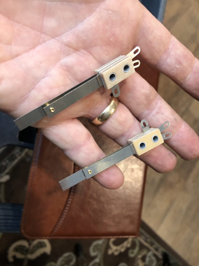
If ordering new flipper mechs (the entire assembly) from PBL – note that on the Harlem title (and likely others with 3 lower flippers) the double flipper arrangement on the left side of the playfield has at least one mech that includes a “double switch” that controls current flow to the second. When you order these Bally flipper mechs from PBL, they all come with the same single EOS switch. You’ll need to source the correct switch or use the old/existing one. I ordered my replacement from Ministry over in England because I could not find the exact part here in the states. I’m betting you could construct one from locally sources parts but I wanted something as plug and play. The switch arrived from overseas in about 2 weeks time. EDIT: I posted the link to this blog post on Pinside and Ken Layton commented that this switch can easily be constructed as follows. Way easier to source it here in the US and get it fast too – thx Ken.
For that double stacked flipper end of stroke switch assembly, you make it up with one each of the two following switches:
ASW-A20-34 Normally closed EOS switch
https://www.marcospecialties.com/pinball-parts/ASW-A20-34
ASW-A10-45 Normally open EOS switch
https://www.marcospecialties.com/pinball-parts/ASW-A10-45
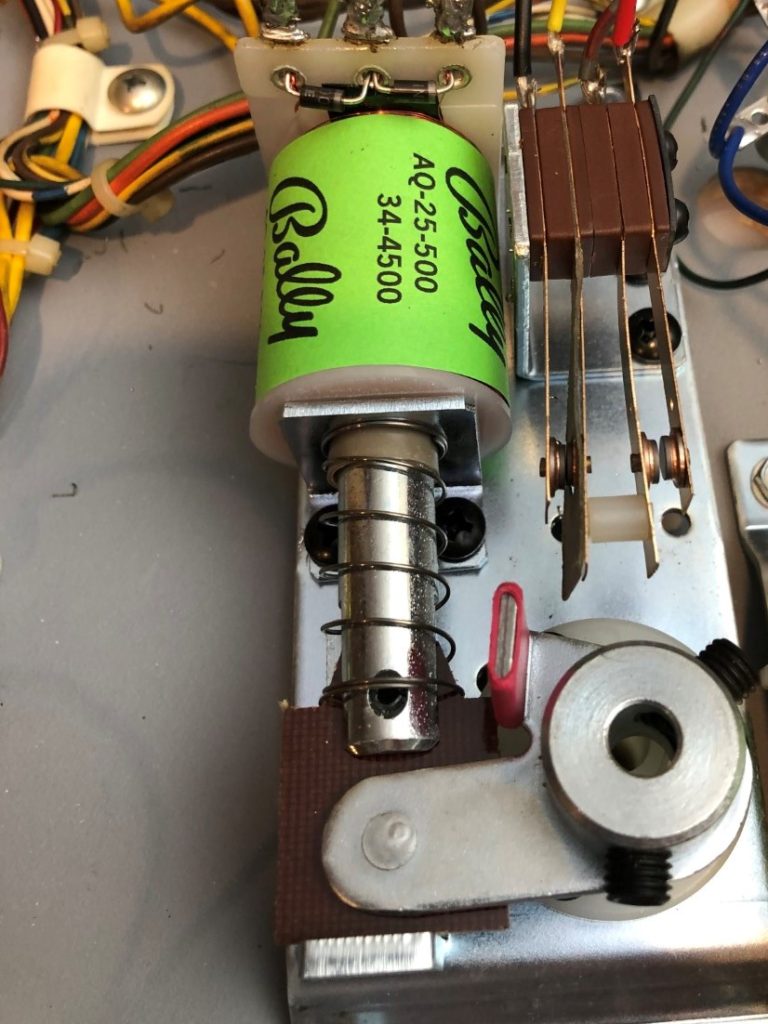
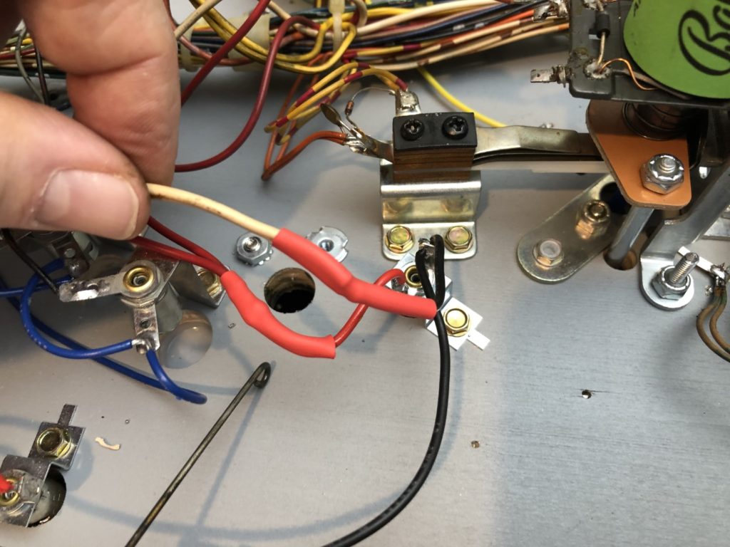
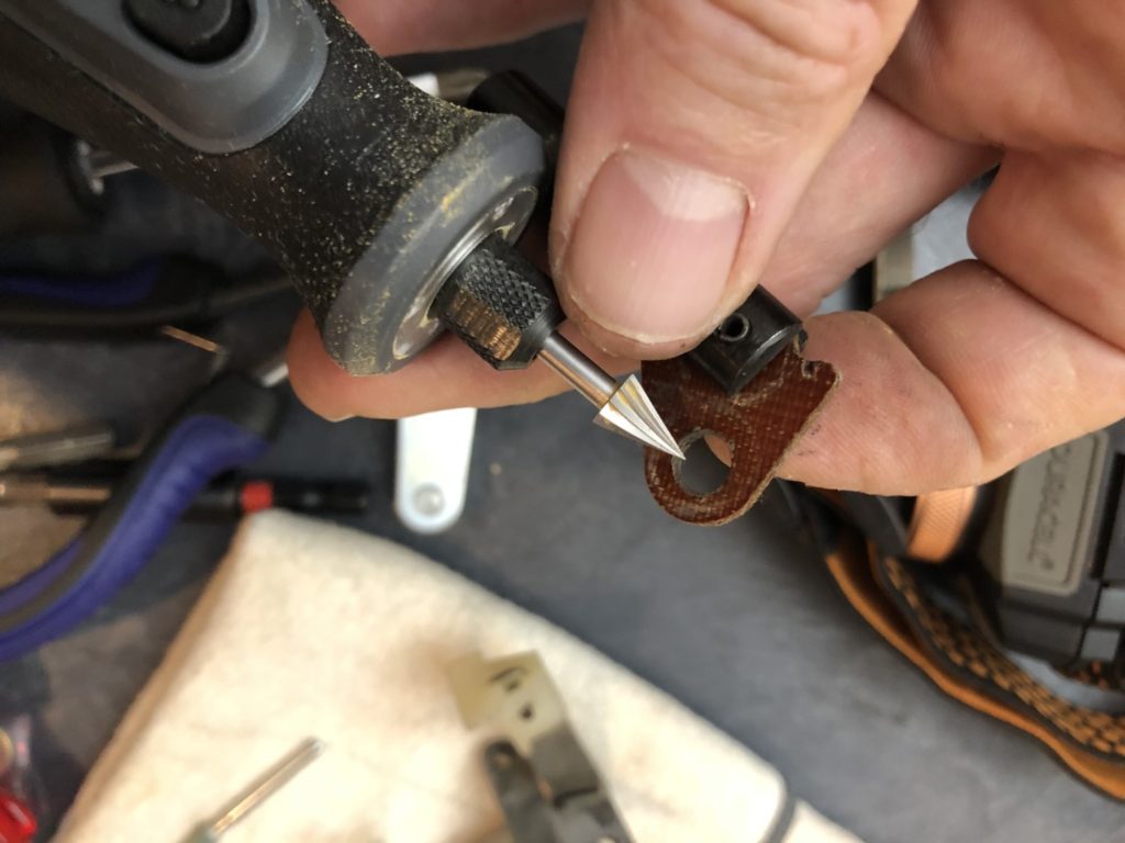
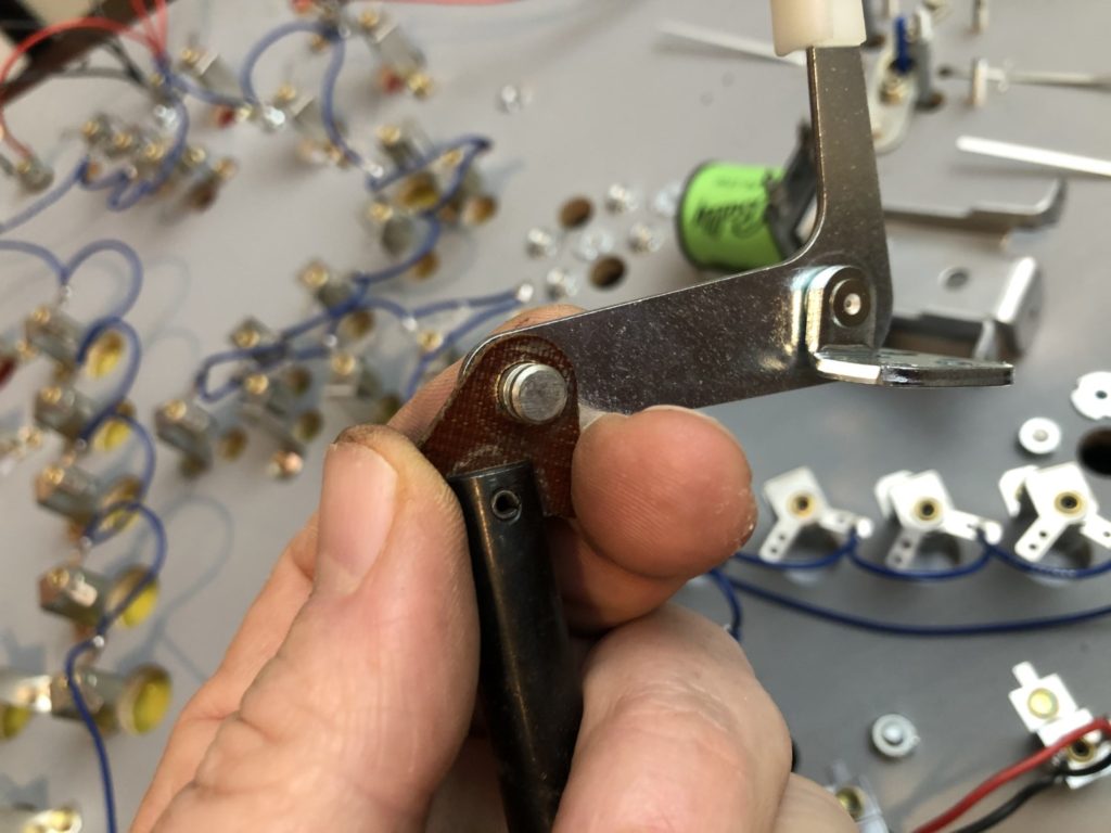
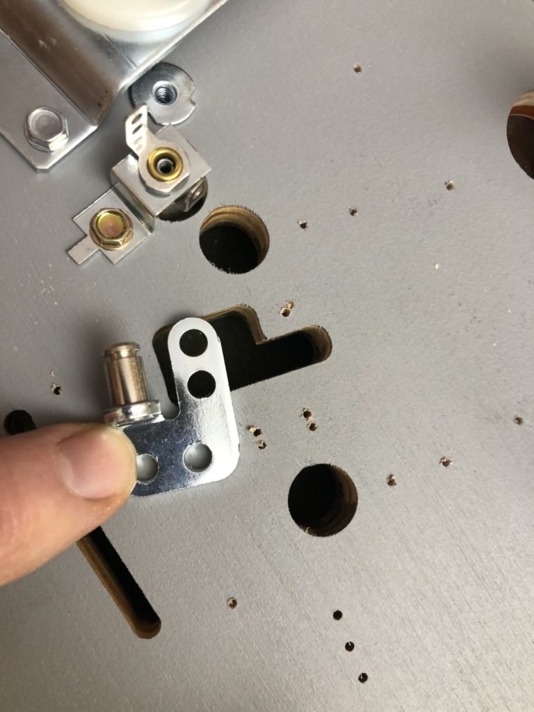
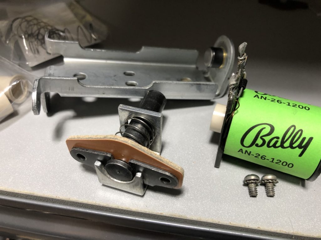
One of the last solenoids to be remounted to the new playfield was the gate switch on the right side outlanes. When something goes “wrong” with a Harlem machine, lots of times it’s this gate. From what I understand, the solenoid is energized nearly 100% of the time to keep the outlane open and only becomes “not energized” when the ball save function is in play. I carefully inspected all the parts, pulled the entire mech apart and hand polished the metal flats.
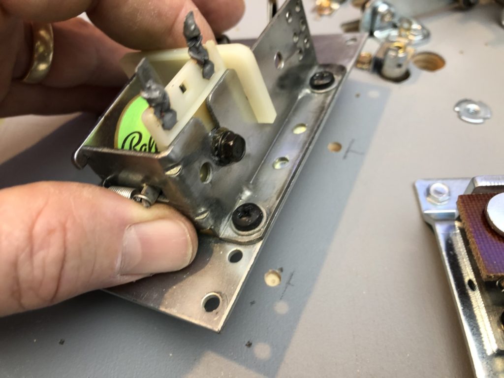
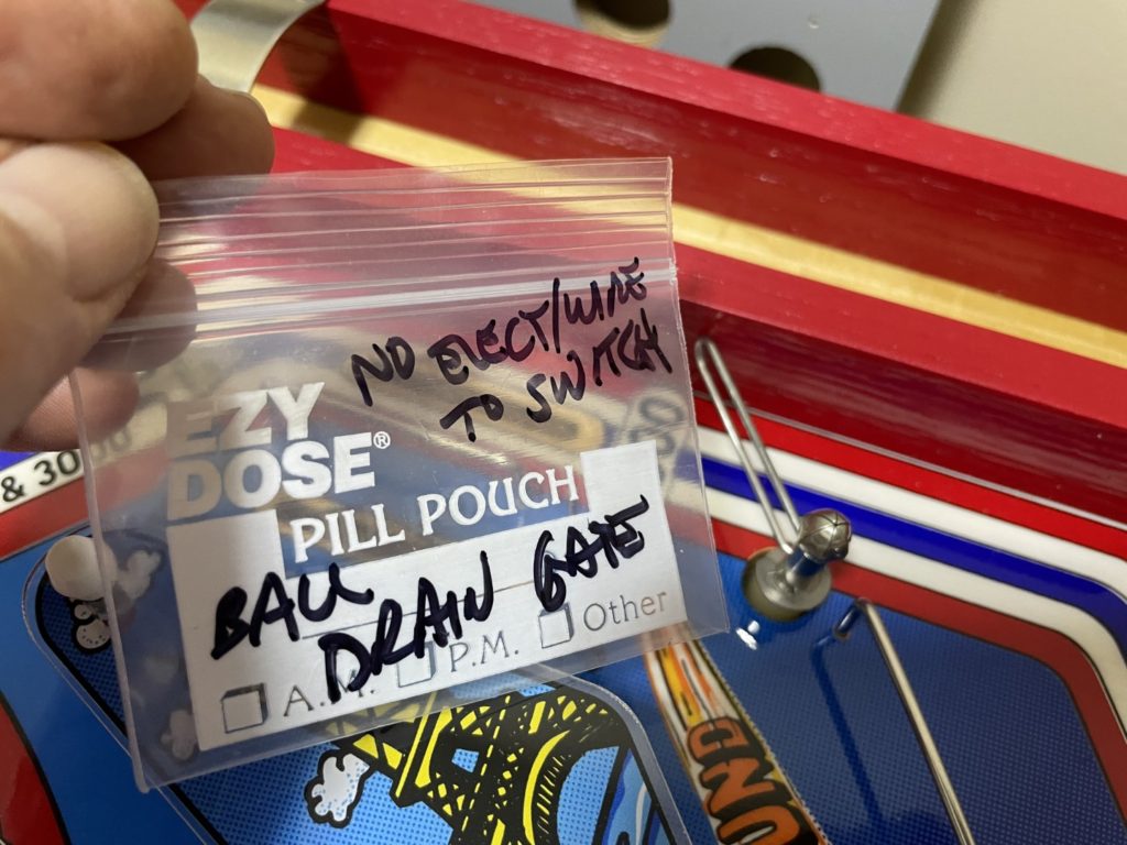
The disassembly was needed for 2 reasons – I wanted to ensure it was 100% clean and functional and I needed to wrap that tiny little coil with a brand spanking new coil wrapper (in Neenah Creative Collection, #98710 in Avacodo green). I was able to quickly locate the associated parts because I made a habit of putting important/unique parts into small baggies and labeling them for later. My gate components looked excellent even if the old coil wrapper looked a little “cooked” it was not burned and when I first bought the game, was fully functional. I finished cleaning the mech, wrapped the coil and pretty quickly had it mounted back to the playfield.
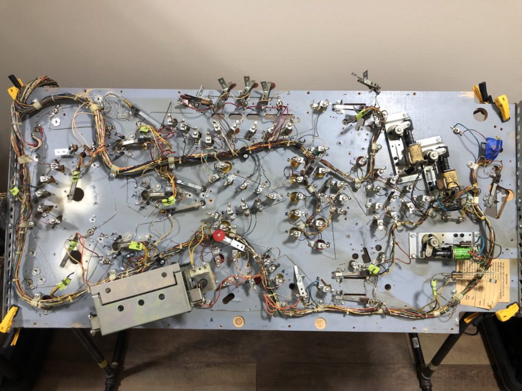
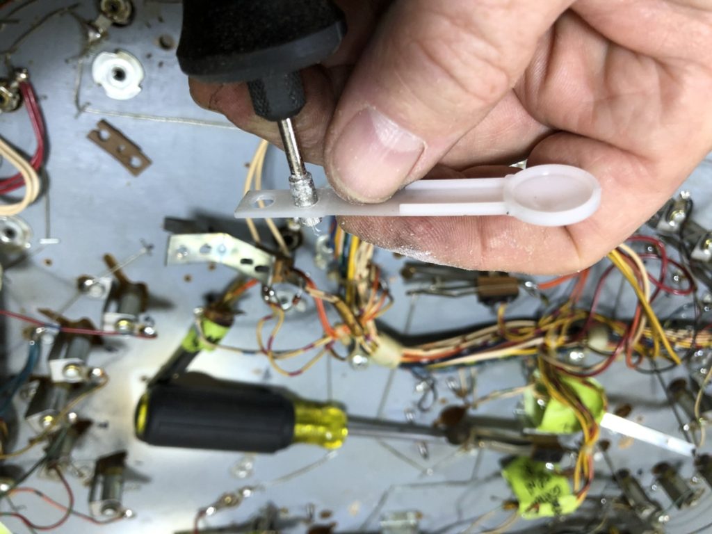
Wow … everytime I think Ive hit a milestone and really accomplished something on the restoration, I’ll start some new part of the project and realize just how little I have done so far AND how much is yet in front of me. Thus the big delay between getting the coil mechs mounted and me taking the next step. The game sat untouched for 3 weeks up in the game room. What was I waiting for? Simple, encouragement, bravery, counsel … you name it. This was the scary part of the restore. I needed to unsolder the old wire harness and move it to the new playfield, then solder it back in. That sounds easy. Holy cow … as you’ll see, not really.
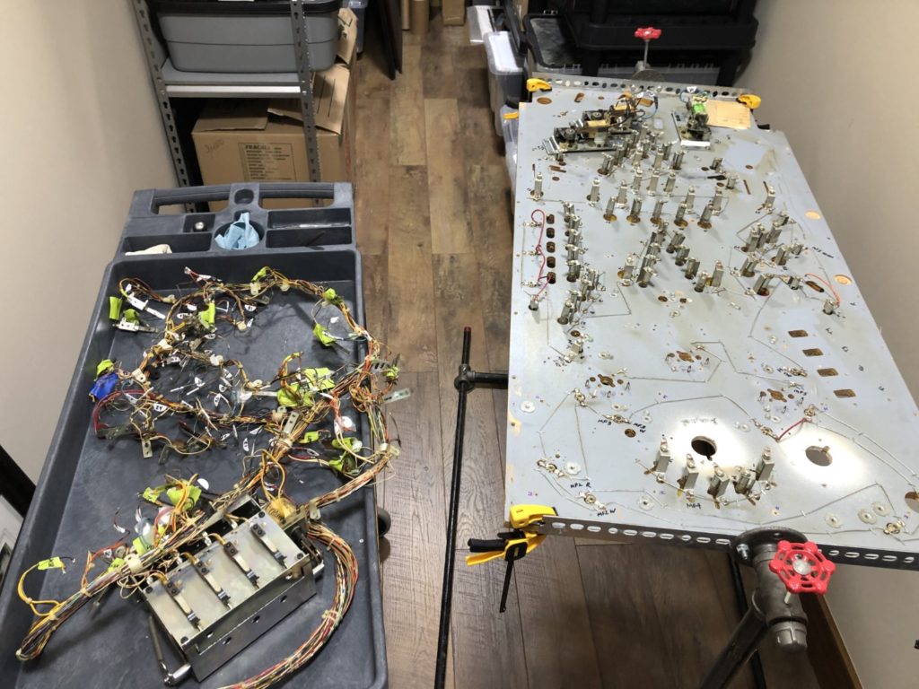
I was stalling for sure. Stalling because I just did not know what the VERY FIRST step should be. Finally I decided to do the most obvious – label everything. So I used my sharpie to write a code number next to each bulb and switch. There were a total of 56 bulbs between the controlled lamps and the GI and more than a dozen switches and mechs to document. Once I finished labeling the playfield, I then captured all the data on my tablet (and emailed a copy to myself so I did not lose it!). I felt better after completing this task. I had finally taken the first step to removing the harness from the PF. So now what? Well to be honest, I was stuck for another week. I finally came back to the original idea that got me moving in the first place – labeling. I asked Tami if she had any garage sale style price stickers. She searched for a bit and found me a pack of white ones – about 5/8″ diameter. I ran up to the Loft and began to write the same code that was written on the playfield onto each of the stickers, then sticking them to each corresponding wire. When I was done, it looked like a mess BUT a mess created by somebody with a plan. I didn’t know if at the time but this last step proved critical later in the process to drive both speed and accuracy.
Now that I had the playfield notated, the wire color data captured in my tablet AND the wires tagged with stickers, I had the confidence to start disconnecting the harness. That part went fast. Get you iron nice and hot, hit each solder joint and a gentle tug and it’s free. Repeat that around 200 times and you’ve got a harness that is ready to be removed. The only thing left to do is to unscrew the harness retention screws and stand-offs. Once that is completed, the harness is completely free from the old PF. When de-soldering the harness, you will need to make some decisions about “how far” you’ll go. For instance, I left the entire drop target mech “wired in”. The gains for de-soldering it (easier ability to clean/polish, etc.) were offset by the significant amount of work required.
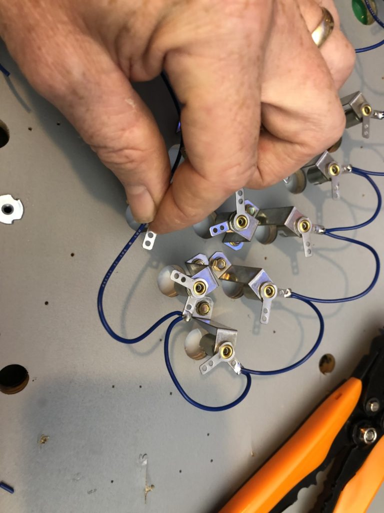
My drop target assembly was clean and the switches were in great shape. So in my opinion, it did not warrant removal. The only minor work (replace the coil sleeve, clean plunger) that needed to be done, could be done once transferred to the new PF. Same story for all the roll over switches – they are under the PF, were in good condition so I left them soldered on. I ALSO left all of the red stand up targets and the sling switches soldered on – although I planned to replace them later, it is WAY easier to just leave them soldered in, carry them to the new PF and then replace them one at a time to ensure correct “wire to blade” placement. This is particularly important when you consider you will be buying new switches – at least in my case the exact/direct replacement was not available. You order a “Bally replacement slingshot scoring switch” and on the surface it looks the same but on closer inspection you’ll find the solder points on the blades may not have the correct sequence or even orientation. This is easily corrected but having the original orientation of the switches still available sure made this easier.
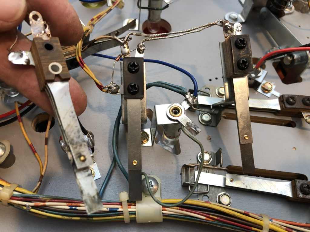
I had pre-ordered about a dozen new switches in anticipation of replacing the sling switches and the other 2 or 3 top side switches that appeared dirty/damaged. I started the process of replacing these at the slings. If you know how the slings are wired on a 70’s era Bally, you’ll know that there is a scoring sling switch and a slave switch. You might have known that BUT I did not. I soldered in the slave switch. What a pain in the but! The slave is connected to the scoring switch by two pieces of braided (bare) wire. I’m thinking, why not keep these wires? They were put there by the engineers on purpose. These switches take a ton of abuse so with all the vibrations and ball strikes, this type of wire probably has the least chance of failure. Not sure that was the right move because de-soldering and reusing braided wire that has solder already embedded in it – is flippin’ painful! As soon as you heat is up it get nice and flexible, but once it cools … well lets just say it gets pretty rigid.
I finally fought it off the old switches (no easy feat) and got it transferred to the new slave switch. I thought I was on my way to get this part done when I took a look at the switch connected to the slave – oh boy … it had another lug/blade/soldering point. Time for a quick order to Pinball Life for the correct switches. I had them in just 3 days and I was eager to get them soldered in. I gathered all my tools and picked up the first switch only to see that although it had the correct lug count, the lugs were not in the correct orientation. I was a bit worried I had ordered the wrong switches when I noticed that the stack could easily be taken apart and re-assembled in the new (correct) order and orientation. That took a few minutes per switch but after that, I was on my way.
Well – the underside is done. The only thing yet to do is mount the switches that connect through the playfield to register the spinners. I purposefully left them unmounted to ensure that the topside components aligned properly. Now that the underside of the playfield was completed, I needed to turn my attention to the PF topside. One problem though. The PF could not be flipped on the table I was using as a work bench. The mechs and solder/wiring would have been damaged. That fact alone delayed my progress by another week as I contemplated how I would move forward. I settled on moving the PF to my home built rotisserie in order to have the flexibility to rotate the PF between the underside and topside. The only negative to using the rotisserie is that you really need to mount the PF to the rotisserie using some screws and washers. Too much of a risk by just using finger clamps. Once I made the decision, I grabbed the PF, moved it to the rotisserie and marked out on the PF underside where the screws would go. On some PFs you get lucky and there is already a mounting screw presented in the exact right spots – not so here. I drilled out 4 small holes and used 3/8″ mounting screws and acrylic fender washers to mount the PF to the rotisserie in a secure manner
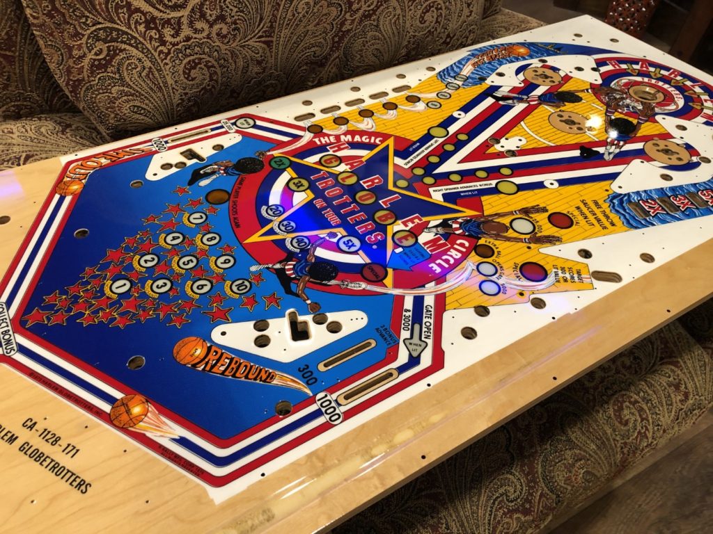
Immediately after flipping the rotisserie mounted PF over to the empty topside, I was struck by how empty it was vs the busy underside I had just completed. I took it all in. That brand new, beautifully clear coated, nearly empty playfield and in the same moment glanced over to the parts containers sitting just a few feet away. Then it hit me. There are not many parts there. Did I lose some? Misplace them? The answer was no. Then the pleasant reality of working the top side of a classic 70’s Bally became apparent – there isn’t much “there”! I was going to (hopefully) get the top of the game repopulated pretty quickly.
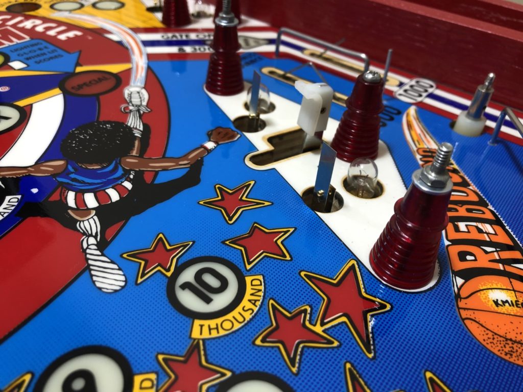
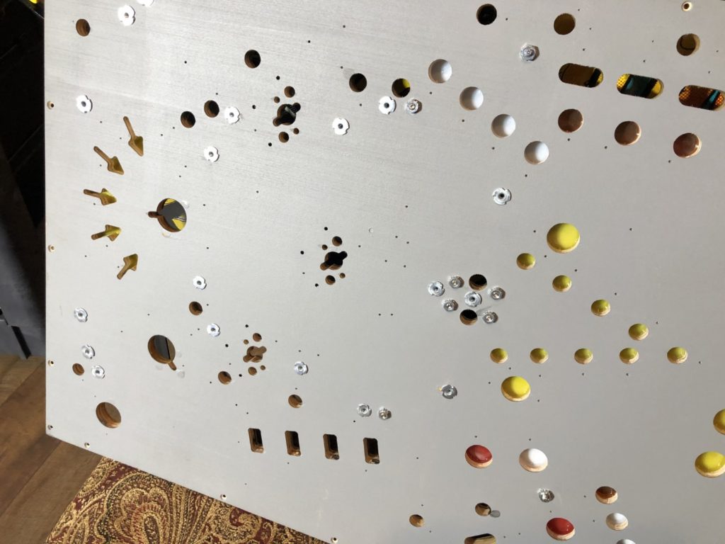
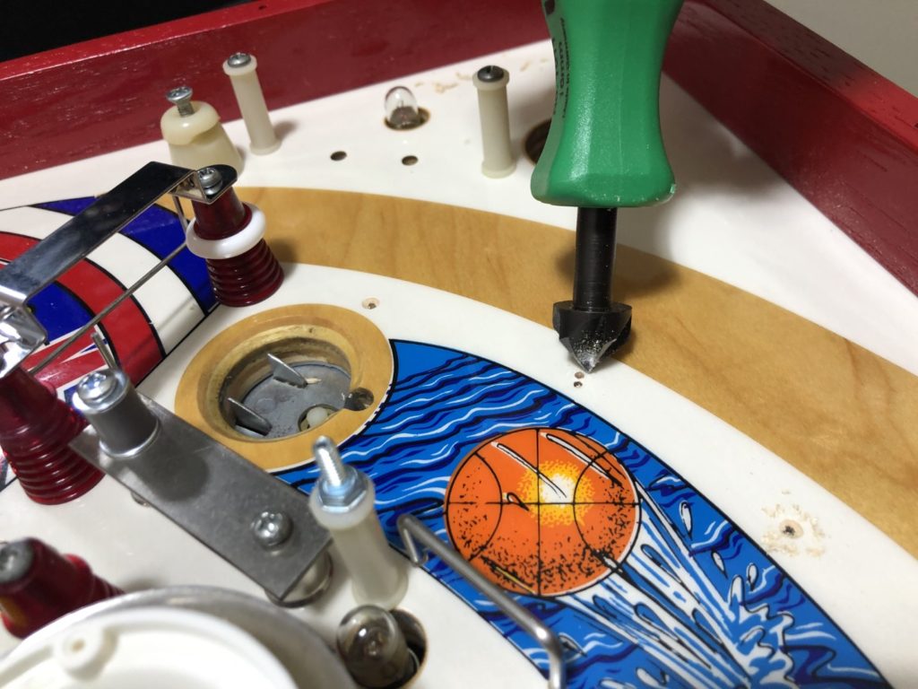
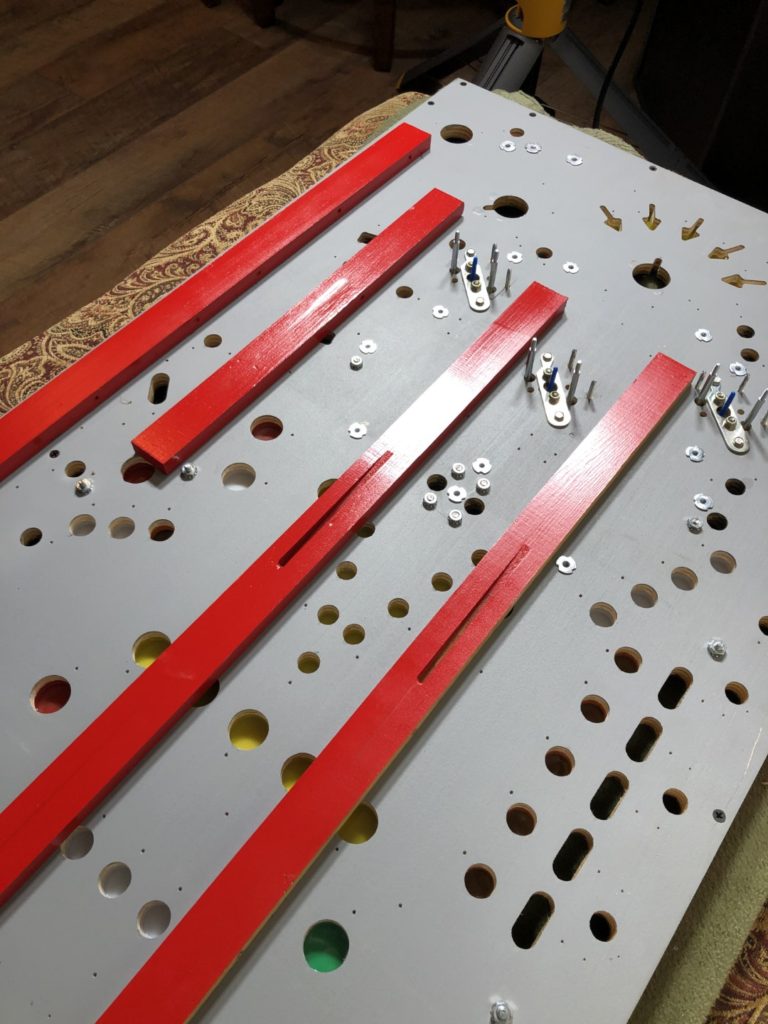
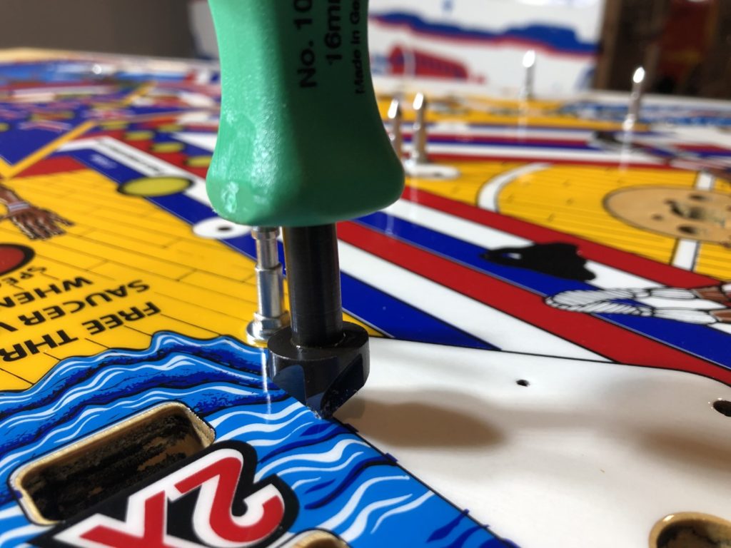
I paused long enough to think through the logical way a game is shopped. My steel mini posts were already installed because I had to hammer in the T-nuts very early on in the process. Now it was time to install all the rest of the posts. Star posts and slim posts. Following that the rubbers and finishing with the plastics set. I started with the lower left sling and worked my way around the playfield, ending with the right sling on the opposite side. I learned a few things along the way. Posts are big- compared to a tiny drilled hole, they are enormous. Big enough in fact that you really never have to worry about the hole you drilled or reamed to remove clear around the edges – remove a generous amount because you will never see it under that huge star post. The learning here was to make sure you remove enough of the clear around each drilled hole to ensure that the clear does not lift when screwing in the posts – even when you think you’ve removed enough clear, check again. I used a hand reamer that allows you to easily control how much, how big and how deep. The best advice I can give is to try this on a post near the top of the PF. Drill the pre-drilled hole to the correct depth and bit size (5/64″ for the HGTOT posts), ream out the clear around the hole, screw in the post fully THEN REMOVE THE POST.
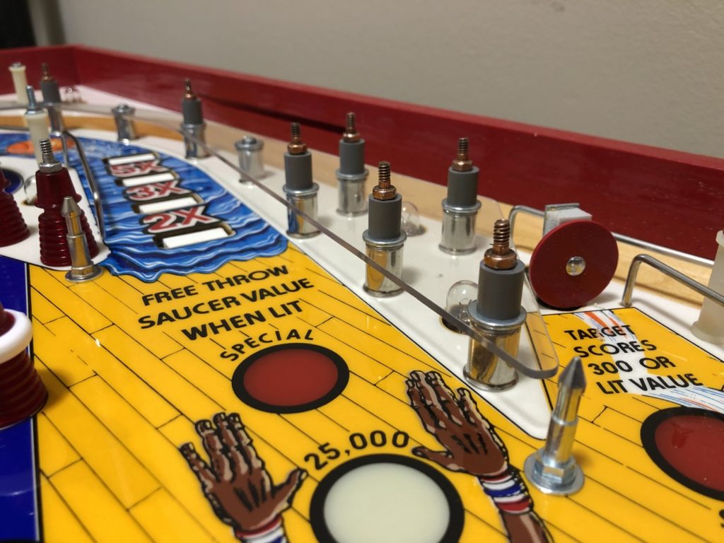
Look at the hole closely, use a magnifying glass if it helps. Look for how the clear coat is behaving near the edge of your drilled hole. Does it start to “turn up” as it nears the hole? Are there obvious signs of lifting/separating? If issues are found, you will need to remove more clear around the hole. A few things to note that might save you some time as you complete this – Note that there is one smaller metal riser vs all the other sizes. Find that one and set it aside, it will be installed on the right side of the playfield just to the right of the drop targets. It’s the 3rd riser down from the top. You can see why Bally designed the riser this way – it’s too close to the ball path and had to be made smaller so it did not interfere with the ball travel. Once I was satisfied that it all looked good – I proceeded to install the remaining posts. I was able to get the posts done in about 4-5 hours.
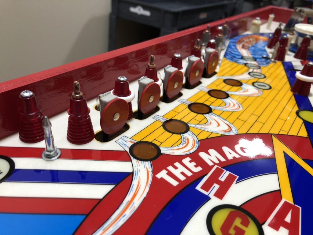
From there I moved to install a bit of the miscellaneous hardware. First piece of hardware I added was the horseshoe shaped ball guide that goes completely around the top of the playfield. Here I discovered something that would have helped from a planning perspective. I should have put a small bit of painters tape around one end to identify the correct orientation before attempting install. As it was, I had removed it, polished it and now stood before the game not knowing where each end went. When you remove that piece, you normally wouldn’t think about that sort of thing – after all, it’s shaped the same way in each direction right? Each half is a mirror of the other right? Well – no. It’s not. If you look closely one end is a bit more “flattened” a the very end vs the other. Of course, when I guessed by just trying it out, I guessed wrong. It just did not fit right into the slots that are milled into the rails. Unfortunately for me, I had purchased brand new Reese rails and once I got the piece seated into those milled slots, it was difficult to get them to release again. I was very worried that I would chip/pull some of the paint from the edges of the milled slots as this steel rod “popped” out. It’s a testament to the paint quality from Reese that even though a put tremendous strain on those milled slots – no paint was removed. After install the large horseshoe ball guide, I went about putting in the one way ball gates at the top of the playfield Rubbers & Plastics
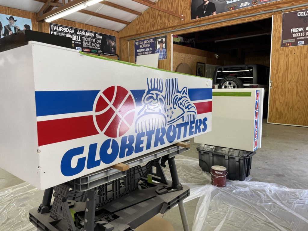
Cabinet Work. Oh boy. So it’s been 6+ months since I finished the topside of the playfield. I figured it was about time that I got busy on the cabinet. Before I started, I had a few decisions to make and tools/parts to gather. What paint would I use? What colors? How would I clearcoat? The most challenging question was … would I chrome it or not? I already had all the new parts ordered that I would need (in brushed stainless) so ordering chrome would add (significantly) to the expense. I decided to go for it. I was this deep, I was going to make it the best it could be. I fired off an email to Chris at Hot Rod Arcade and plating over in Nashville. I needed chrome side rails, shooter rod, lock down bar, grill, coin door bezel, shooter housing, legs, bolts and a few more things. I got a quick email back that he had all my parts and these were the LAST early Bally SS chrome parts he would have for a while (post COVID) parts shortages. I quickly made an appointment to bring my exchange parts to him in person and pick up my new chrome parts as well. Sunday June 13th I fired up the Porsche 911 and headed to Nashville.
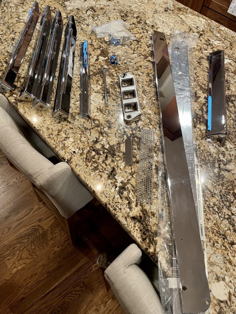
Gosh I almost forgot how much fun this car is to drive. Passing someone at 80 and then watching the RPM max (just under 7K) as you pop the gears is about as much fun as you can have with your clothes on. The car goes from 80 to triple digits in seconds and handles like a slot car (in Super Sport mode) along the way. Takes your breath away. Hoping this Harlem does the same when done! I met Chris at Hot Rod on a Sunday after Church (he is a pastor) and had a great visit. I got to see some beautiful personal machines of his and got a tour of his new Pinball building which was stunning to say the least – brand new and over a hundred feet long with a mezzanine and showroom – wow! Chris was both kind and gracious and when I asked if he had a plated lock down mech, he not only took the time to find one (he did have one) but he gave it to me as a gift. That part will save we several hours of work alone (and it looks fantastic too!)
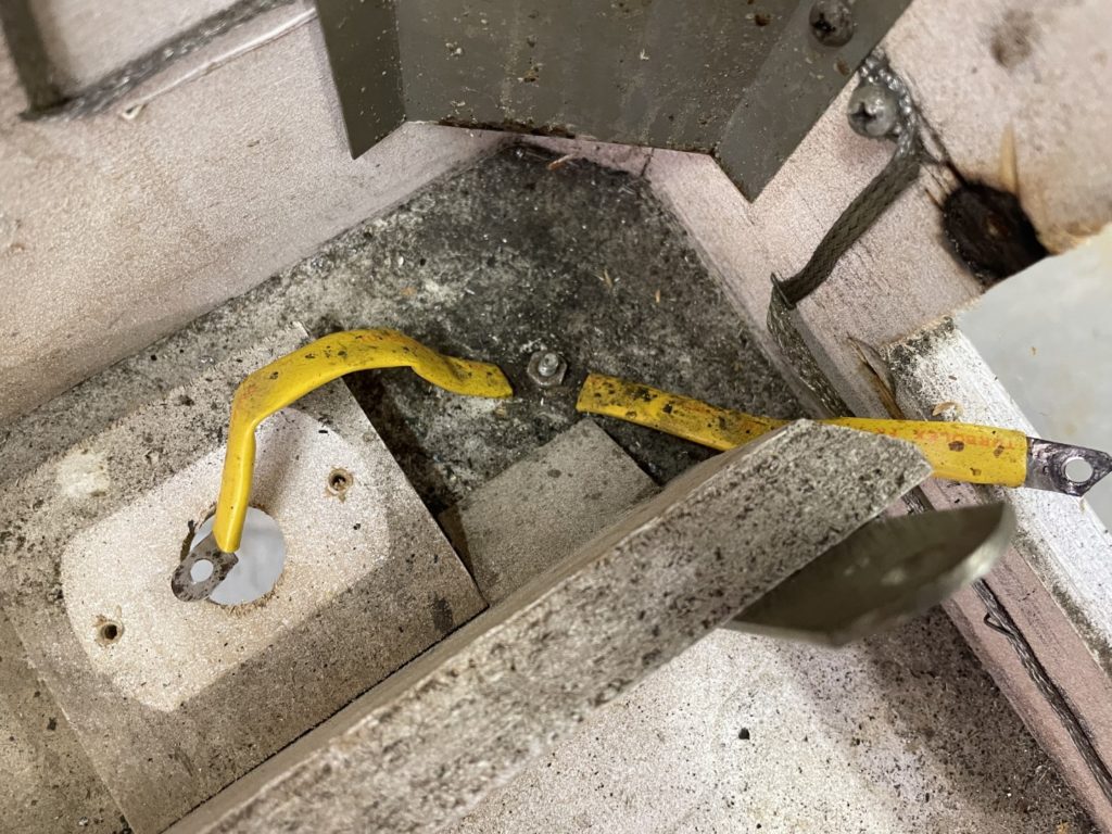
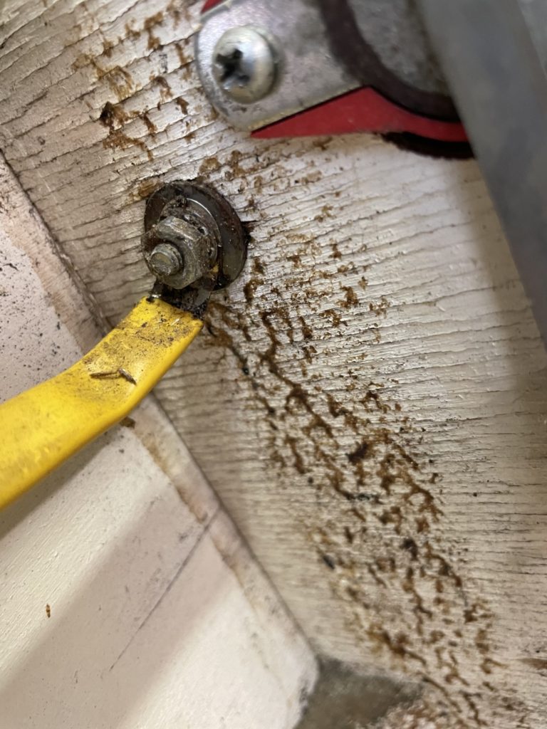
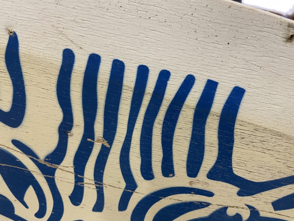
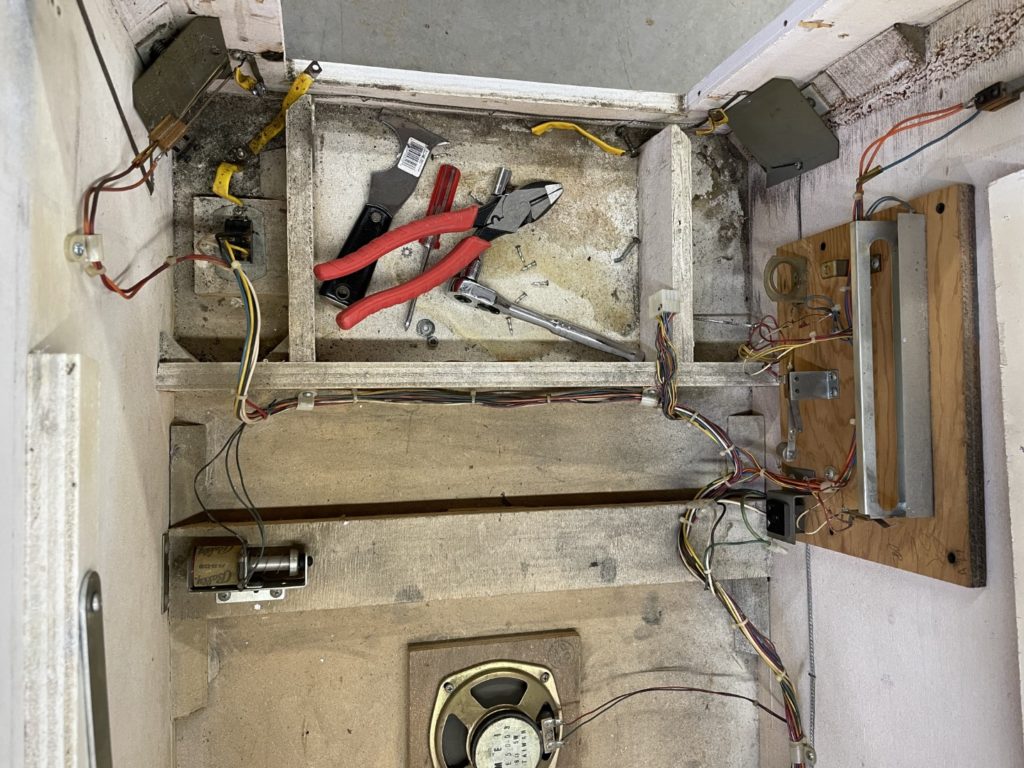
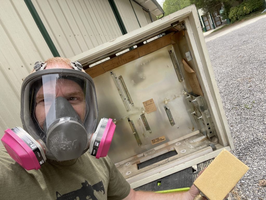
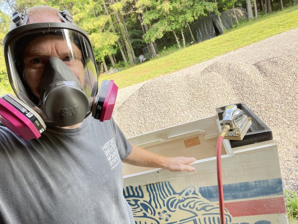
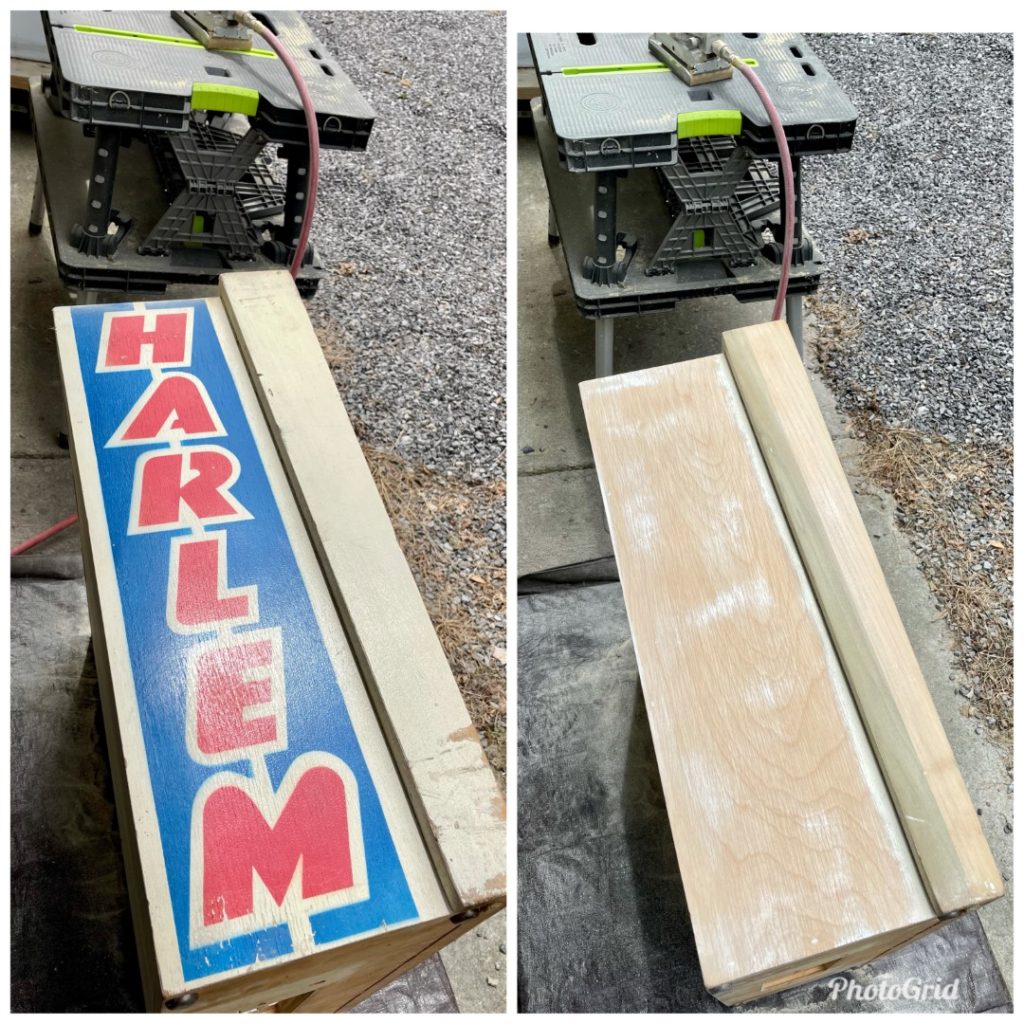
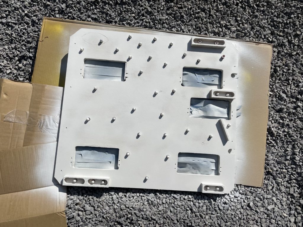
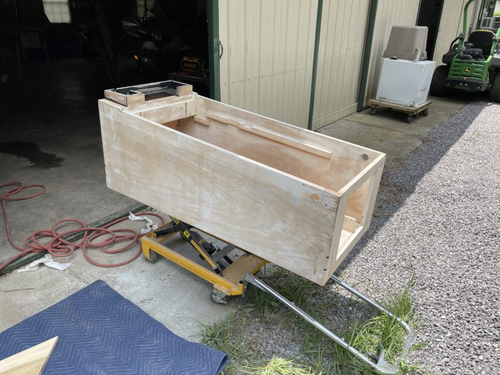
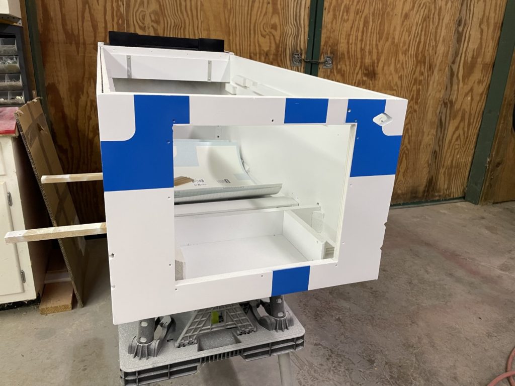
Back home with the parts, it was time to tackle the challenging process of stripping and preparing the cabinet and head for a repaint. I tackled the cabinet first. I had already picked up the needed supplied and had on hand 80/120/220 grit sandpaper, Bondo and a full face mask respirator. I had everything out of the cabinet except the flipper buttons, yellow ground strapping, cabinet speaker, side rails, knocker, ground braid, tilt mech, varistor, prop rod, power wires/switch and front glass channel. It took a few hours to pull all of that … mostly due to a rusted nut that spun on the threads for one of the front end side rail carriage bolts – I finally cut it off with a Dremel. Ugh.
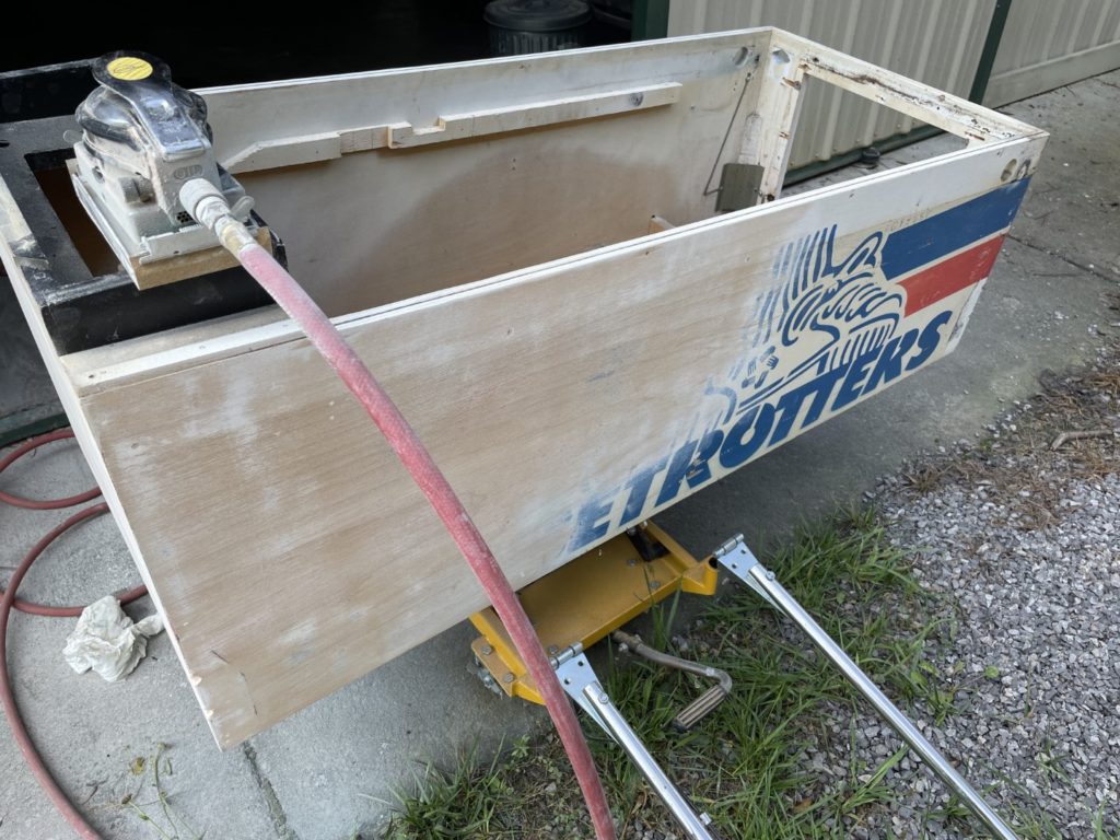
With the cabinet stripped of hardware it was time to go to town. This part is simply messy. The work is straightforward though. Sand with 80 grit to remove the paint. Mark all the small knicks, depressions, gouges with a pencil, mix and add Bondo to those marked areas, let it set up (I did overnight) and sand again with 80 grit. Once the Bondo work is done, move to 120 grit to remove the 80 grit swirl marks, then finish with 120 grit to a super smooth finish for priming. I use a large compressor from Harbor Freight and a cheap orbital air sander. Works like a charm but performs best in the 80-100 PSI range and even my large compressor is running constantly when I’m sanding. When the PSI dropped below 70 or so, I just took a break to let it catch up. If you put pressure on the tool (especially with 80 grit) when the PSI is low and the tool is not orbiting fast, you’ll leave more swirl marks. Sanding the back panel of the cabinet and head were the most challenging because those are press board and the paint really soaked in when they were originally sprayed.
When I finished sanding the 80 grit I noticed the bottom mason board of the cabinet was a little “loose” in the center of the cab. It was loose but not in danger of coming out or dropping out the bottom. The slot that it rides in was secure both top and bottom but over time the wood had shrunk by a few millimeters and the glue had let go as well. I spent a few days wondering how to best repair it and settled on the simplest approach. I used a plastic pry bar to open the joint and turned the cabinet on it’s side, then shot some Titebond III glue into the joint. I did the same on the other side as well. Once finished, I put the cabinet on the HF lift, added some poplar shims right under my repair to “push up” on the mason board bottom and watched as the glue joint tightened and squeezed the extra glue out. I used a wet cloth to clean the extra glue off the joint and let it dry overnight. The next day the joint was tight and looked factory fresh again.
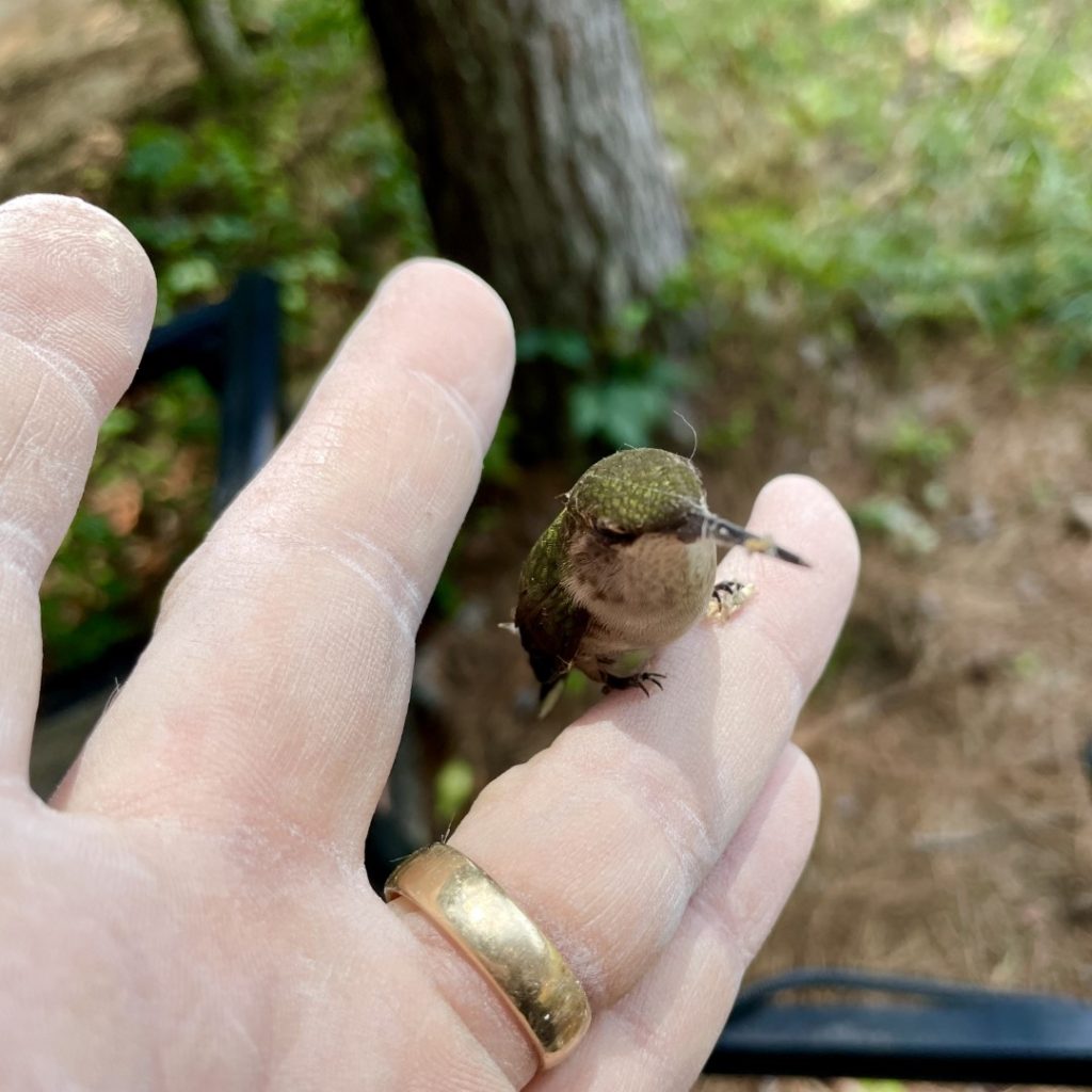
As I was cleaning up a hummingbird flew into the pole barn. Bummer, as they usually don’t find their way out. This one finally exhausted himself and fell to the floor in a corner and got tangled up in spiderwebs. I went over there, picked him up and carefully cleaned off the mess. I took him back outside and he sat on my finger for 3 or 4 minutes catching his breath. Finally he lifted off my hand and landed in a branch a few feet above my head. Rescue complete.
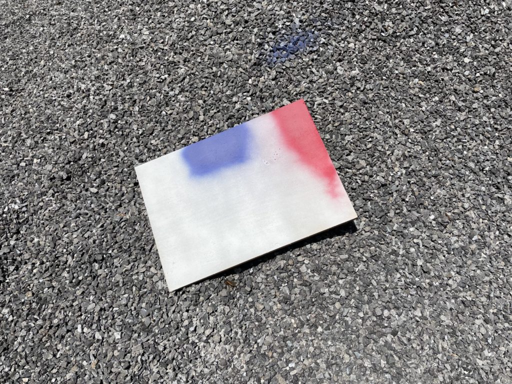
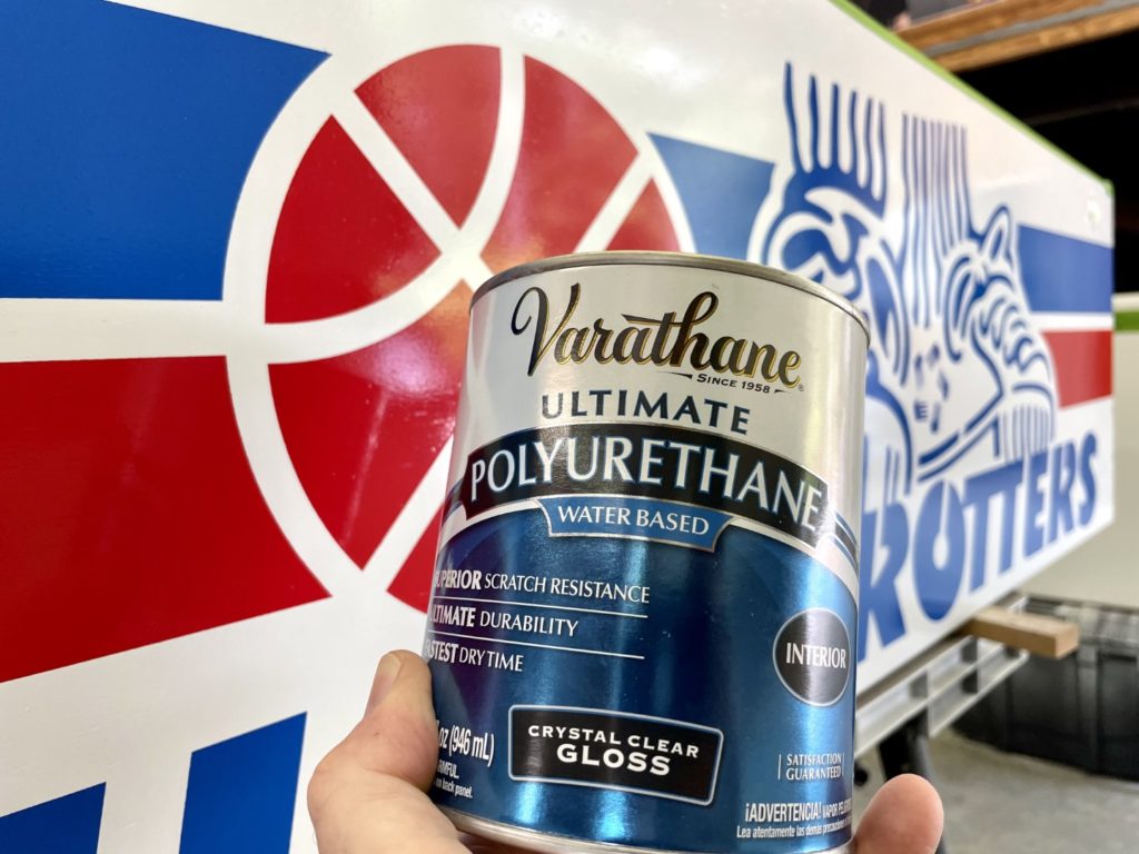
Before I finished the cabinet prep, I needed to make a plan for painting it. I settled in Molotow paints (rattle cans). Ordering the paint online has the advantage if saving a few pennies (doesn’t matter a ton here because you’ll be hard pressed to find Molotow locally) but the big disadvantage is that you can “really” know of the colors are correct. Lot’s of folks have specified the colors for Harlem – but they are always the paint you can buy in Home Depot (think Rustoleum). When the Molotow arrived, I needed to run some paint tests to be sure. so I grabbed a scrap of plywood, painted it with the Kilz original (oil based) primer that I had already bought and sprayed the entire piece with Molotow “Signal White”. I let that dry overnight before then laying down a section of Molotow blue (xx) and Molotow red (xx). To be honest, the colors looked great! Not too bright (primary) and they pop enough on the white to really call attention to the combo. I was pleased. From there I needed to make a call on if/how I would seal or clear coat the final paint job. The easy answer was Varathane – the paint it on with a brush style, water based Varathane. Easy enough to try it so I grabbed a quart of the gloss finish at HD and put two coats on top of the test color board. Importantly, it did not react with the paint – critical test #1 passed. It looked good too. More of a satin finish though. If I land on this as my final decision, it will look great and be very easy to finish. (I switched all cabinet paint to Rustoleum after trialing the Molotow. It was a flat paint and was too easily marked and became dirty quickly. I was also worried about the final finish. I wanted a fairly high shine and I was not convinced that the Molotow would give me that with the Varathane cover coat. As you’ll see in a bit – the Rustoleum did.
That same evening I headed back to the house (midnight) to shower and decided that before I called it a night, I should pull my Pinball Pimp stencils out of the shipping tube and get them flattened out for use. 10 minutes later, I had them stretched out on the floor in the loft with heavy books on each end. Glad I remembered that BEFORE I needed them
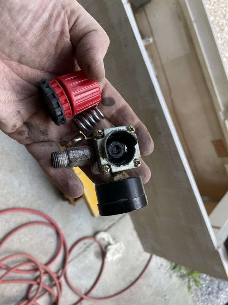
A few days later, I was back in the pole barn ready to move to the 120 grit paper. It was a hot as heck Saturday and I was taking a break and talking to my buddy when I heard a “pop” and a release of air from my compressor. Thinking it was the high pressure release valve (and not hearing anything else) I ignored it. When I came back to resume sanding, I had no air pressure. The “pop” I heard was the 29 cent regulator that HF puts on these compressors. It blew the top right off it, ripped the adjuster right off the threads. Looks like it’s super cheap white metal. A quick trip to Home Depot and I found at least 3 regulators in the tool section that could be used to replace mine. I grabbed the adjustable one, headed home and was back sanding in minutes.
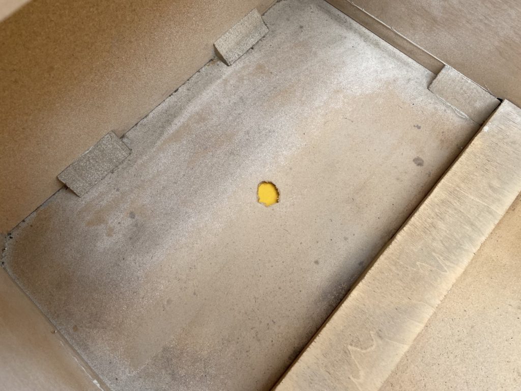
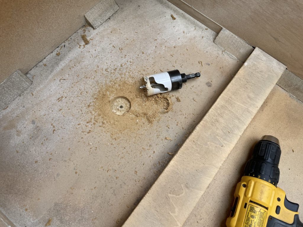
I finished the 120 rit and was happy with the results. It was time to “fix” something that was nagging at me for a while. A hole in the cabinet bottom. Somebody had literally gouged a hole in the mason board bottom of the cabinet. I’m guessing they moved the machine, put the head back on and forgot the thread the power cord into the slot provided in the head. Rather than removed the 4 bolts they just put in, they grabbed a screwdriver and shoved it through the bottom of the cabinet. I wondered how I might fix it or, at a minimum, make it look better. I settled on “look better” and grabbed a scrap of poplar, put it under the gouged out hole and used a hole saw that was just slightly larger than the hole to create a new, nicely round hole of about 2″ in diameter. I’ll probably just leave it at that. It looks so much better.
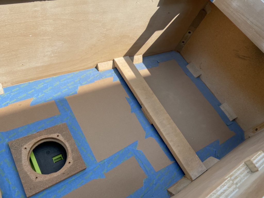
With the 120 grit done, it was time for the final 220 grit sanding and prep before priming. I did the outside of the cabinet first and then moved the inside. The inside slowed me down because I wanted to keep the bottom panel “original”. This meant quite a bit of “clean up” and hand sanding in the base area. As you might expect, 40 years of stains and dirt are not kind the bottom of a pinball cabinet. I used the palm sander to get most of the panel cleaned up, then on to a hand block sander to get the edges. I took a few minutes to cut off all the old/exposed glue from the corner blocking that squeezed out when the cabinet was originally constructed. When I was done the panel looked great, but the area where the coin box sits did not. There would be no way to clean that up so I made the decision to paint that section white. The remainder of the bottom panel would be taped off and left “natural”.
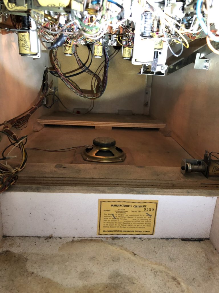
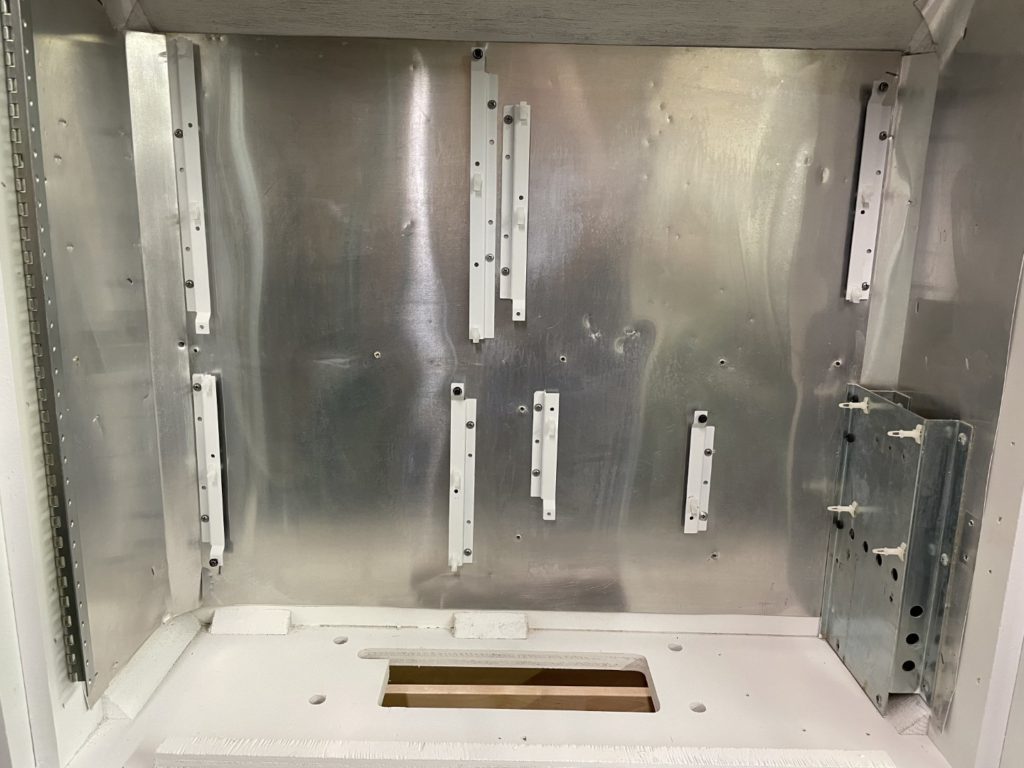
It was time to tackle that back box. Oh boy. Lots going on in there. I debated leaving the boards in there but decided that I had come this far and should take the extra steps to finish the inside of the backbox as well. I photographed, then unplugged the light/display panel. I removed the screws holding the light panel piano hinge and removed the entire panel. The face of it would get a paint job, but the rear will not. That’s an added step I want to avoid (and can be done later if I so choose). Next the board were removed, then the transformer. Finally, each of the instruction and safety cards that are stapled to the back box were carefully removed as well. The “careful” part was all about being mindful of the metal ground plane material and careful not to damage it. I was not worried about the cards as I was able to get new ones and print them myself from Ichnochko site. Pulling those staples is a big pain and I used a hooked beak Milwaukee electricians knife to great effect. The staples in into the back panel were the most challenging because they are stapled into pressboard not real wood. After that the only part left to remove what the short piece if ground braid that connects the left and right side of the metal plates in the head and provides a connection to the ground braid into the cabinet. A few staples later and that was out as well.
Sanding the head was quick and the only challenges were the back (takes longer) and the narrow edges (being careful to keep sander level). I finished sanding and added the Bondo in the same session.
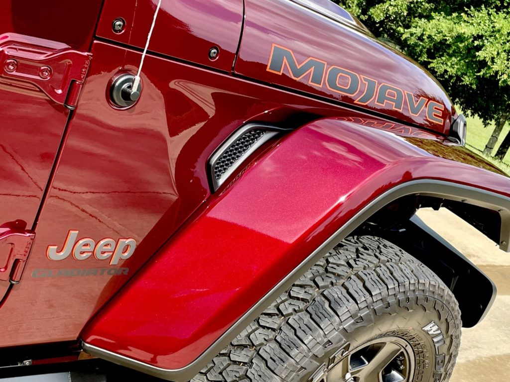
I took a night off to go buy a new Jeep. My 2017 Ford F150 King Ranch had 75,000 miles on it and (so I heard) it was now worth the “most it would ever be” vs what I had paid for it. I looked online at KBB and sure enough, its blue book value in trade was $41K. I only paid $55K or so when I bought it 4 years prior. So I drove over to Harper where I’ve bought (too many) cars in the past. They have the best service in the nation, are very fair on pricing, treat their customers like kings and … offer a lifetime powertrain warranty. I still needed a truck for hauling things around the ranch so, it did not make sense to go back into a $70K full sized pickup. The Jeep Gladiator fit the bill perfectly. Harper had 2 Gladiators on the lot – a “Sarge Green” and “Snazzberry Pearlcoat” and both in the Mojave feature sets. I got the Snazzberry one. Added some Predator Pro step bars, some floor mats, sill protectors, fire extinguisher and a Diamondback HD bed cover to finish it off. It’s a nice truck.
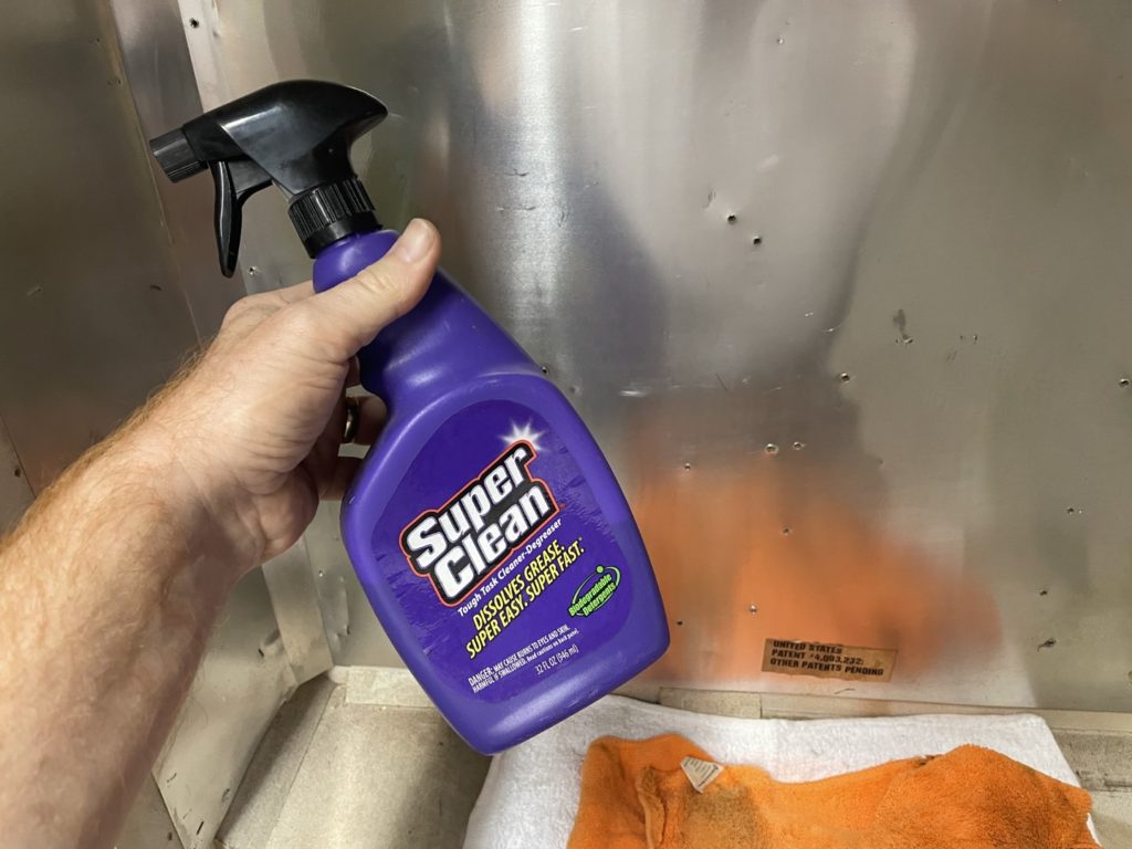
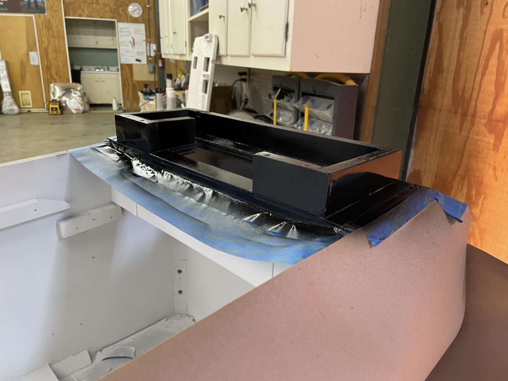
Back to the Globetrotters back box. I spent a few minutes pulling the circuit board rails off the back box and using every single cleaner in my cabinet to remove the “nicotine brown” stains that were all over the metal plates behind them – to no avail. I posted to Pinside looking for some help and Bryan Kelly shared that he used “Purple Power” to get it off. I didnt have time that evening to stop at the store to get a bottle BUT I remembered that I had used a similar spary to clean the cabinet on my Twin Win not too long ago. When I got home I found the bottle. It was called “Super Clean” degreaser. I grabbed it, sprayed a bit on a towel to test it and almost immediately saw the white towel turn brown. I quickly sprayed the entire metal sheet with the degreaser and watched excitedly as the brown stain just melted away and dripped down the toward the bottom of the head. 2 minutes later the entire backbox was done and looked great! I spent the next 45 minutes taping off the metal ground plates and the associated hardware that would not be removed before painting.
I popped back into the Pole barn a day later, keen on getting the backbox ready to be primed. I notice the light panel sitting there all smoke stained from the incandescent bulbs. I couldnt walk by it. I picked it up and surveyed the amount of work it would be to “get it taken care of”. The answer was not much IF I ignored the back. So I ignored the back. Took about 10 minutes to pull the displays and about 20 minutes to tape the panel off (cover the display cut outs) and pop some old buls in there so as to not spray the innards of the bulb fixtures. I got all that done and dragged it outside to the gravel pile (right outside the pole barn) and layed down a coat of Kilz. An hour later I added the coat of Molotow Signal White and with that was done with the light panel.
The next night was focused on the back box and in just a few minutes, I had all the bondo sanded down level and had run a sheet of 220 grit to make it all smooth. That all went so quickly that I had time left over to focus on prepping the main cabinet for primer. First I would need to tape off the bottom board as the plan fwas to leave that as natural wood. Before I could lay down my tape, I needed to sand the inside corners to remove a tiny bit of glue residue from my recent work in gluing up the bottom board. Sanding off glue “haze” is a bit harder that it would seem. What felt like a month later – I was finally done. I cut a few sheets of masking paper and test fit them in the cabinet before I finally had to call it a day and head back to the house.
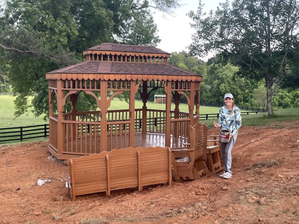
The weekend was here and I had high hopes of getting a lot done on the game. Not so much as it turned out. I spent much of my time doing various bits of ranch work that was either needed or part of a plan to prepare for the 2 events coming up – the Porsche Club social event (expecting up to 100 people) or my daughter’s wedding. I ended up putting in a 3 car gravel parking lot, replacing the faucet and drain in the pole barn guest bath and hanging new pictures in the Pole Barn office. That was just at one building. On the front of the property I spray stained a new gazebo that miss Tami bought for future parties/weddings and events (she is starting a new business). We washed a few cars, cleaned the garage and finally built a new beverage storage rack for the garage area. By the time Sunday came, not much had happened on Harlem so I mosied on over to the barn and decided to fire up the new polisher I had bought. It was a good time to test it out on the many pieces of hardware that needed cleaning and polishing on Harlem. I learned a bunch about the polishing process. Flat pieces without holes work better. Larger pieces are better. Using various grades (courser to finer) ends in a better result, etc. etc. In the end I finished with a real nice high polish finish on one side of the lock down bar. It was nearly “chrome like” and I was both surprised and pleased with the result. I’ll just need to choose the pieces I decide to polish with the machine carefully vs ones I will hand polish.
I got back into the barn for a few hours to tackle the base of the cabinet. It was all sanded and ready to be protected from the deluge of paint that was headed it’s way. I taped the edges using blue painters tape, then added pieces of masking paper to fit the larger areas. When completed, the cross bracing and corner bracing was (purposefully) left exposed and the bare masonite board was protected in order to remain brown/bare when the entire cab was completed. I found later that the tape did a great job at the edges (stuck to the bare masonite) but did not “stay stuck” where it was asked to stick to itself. Knowing this now, I would have run a few strips of duct tape from the first row of my blue (against the edge) and connecting that to the masking paper. I took a peek under the paper and saw very little overspray so in the end all is well but why not fix it and not have to worry.
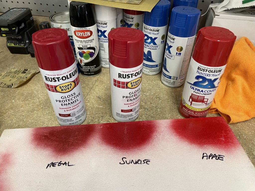
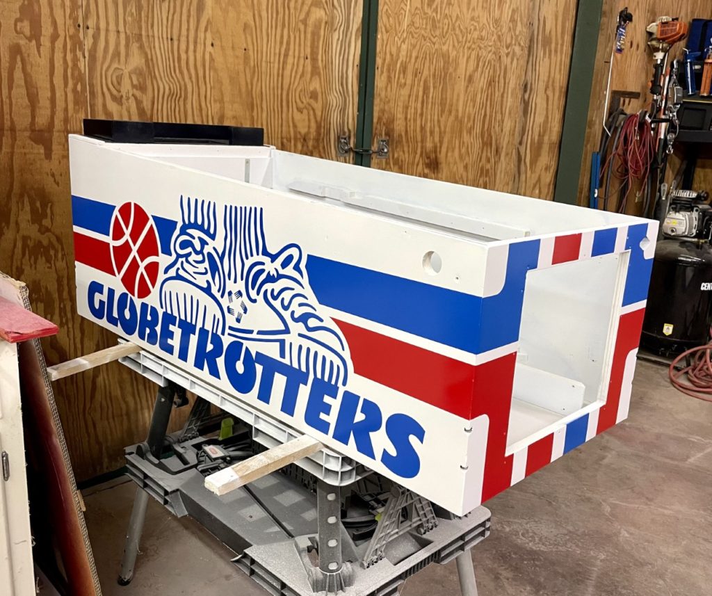
Holy cow! Lot’s of work completed over the past few days. It seems like the more I get done at this point, the more the list of “things to do” grows in defiance. I now understand the phrase “prime, sand, prime, sand” much better than I did before. At this point, the cabinet is down to bare wood. I’ve sanded it using the 80/120/220 paper and my trusty air powered orbital palm sander. There is still one side of the exterior of the cabinet that has a bunch of wood grain but no amount of sanding will remove it – it just keeps exposing more. To fix that, I’ll need to add primer, sand it back to the surface of the wood and repeat until those wood grain “depressions” are filled in. I did just that and although not 100%, I’ve got it good enough (4 steps of prime/sand) for a final prime. I layed down that last coat of Kilz primer and lightly sanded using the 220 grit paper. I let that dry for a full day before attempting to add the first basecoat. That gave me time to think – maybe too much time. Was Molotow the right paint? Were the colors I chose even the right colors? I asked that of myself because the Molotow is a flat paint and in testing, it was difficult to even see where I had placed the basecoat over the Kilz primer. What if I decide not to clear coat the cabinet? Flat paint is easily marred and damaged. I turned my attention to the 2 colors I had chosen for the red and blue HGT logo. The blue looked to purple and the red looked too blue. Was I seeing things? I remembered that a year ago, someone on Pinside had posted the “right colors” to use (Rustoleum 2x) for HGT. I checked my notes and sure enough, I had copied and saved those colors. Gloss white, brilliant blue and apple red. I ran to the local Home Depot and picked up a fe wcans of each. When I got back, I sprayed test colors of both the red and blue next to the Molotow colors. I was right. These colors were much closer to the original HGT colors and, as a bonus they were high gloss and even a bit cheaper (not to mention readily available). I moved quickly to prep the cabinet for it’s first basecoat of “glossy white”.
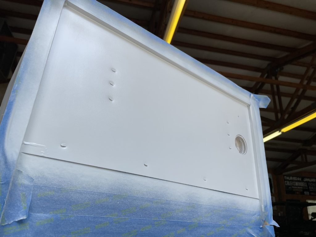
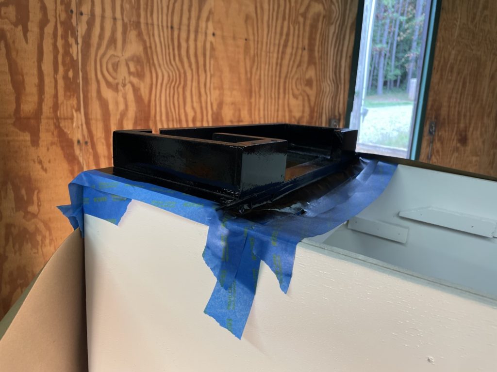
Wait a minute … that metal security plate on the bottom of all Bally cabinets was looking pretty nasty – better address that first. I flipped the cabinet and started polishing. Waste of time. The plate had too much corrosion to be made presentable by polishing. So I sanded it with 220, then taped it off and painted it glossy white. It came out great. Now back to the cabinet topside. Wait a minute … I can’t really paint that bright white until I get the neck area painted black. I took about an hour to tape off the neck area and lay down a coat of Krylon gloss black (that pretty quickly got “speckled” by all subsequent white paint work!) Finally, I was able to put my first basecoat on. Painting white in the bright sun is not something I reccomend. I tried. It’s hard. When I moved to a shady area, the process got easier. I could clearly see how the paint was going down and adjust accordingly. Be prepared for “failures” of any kind. You are using rattle cans and you will likely encounter some troubles. I had two. The first was a spray can failure – about halfway through a can of gloosy white, it started “spitting” little balls of paint. Those balls were coming out nearly dry and as a result “sat” on the surface of the cabinet. Ugh. The last thing I wanted was “texture” in my gloss paint! I carefully flattened as many as I could when they were wet and grabbed a fresh can of paint and continued. Paint on the other side of the cabinet went on smoothly, however I noticed when I was done there were blotchy areas that were “not white” but had a grey tinge to them. I’lll chalk that up to poor mixing on my part and would be much more careful in the future to make sure that each can was adequately mixed before use.
I was dirty, I was covered in paint and although tired I still had the head to address. I could not remember what the current state was when I last left it. A quick look (and feel) demonstrated that it had the final primer coat on and simply needed a final 220 sanding and it would be ready for the first base coat. It took just a few minutes to sand the backbox and only a few more to add the first basecoat.
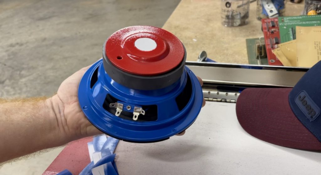
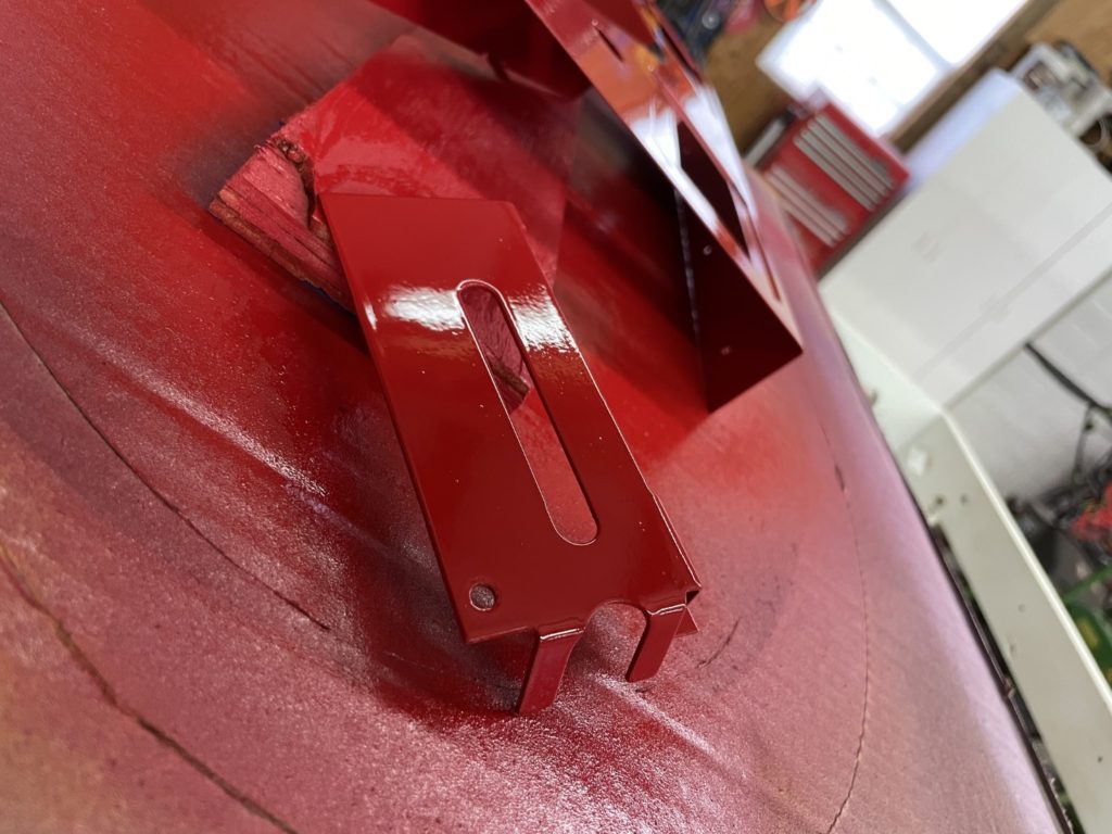
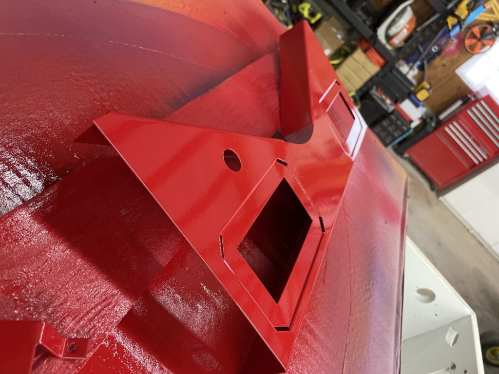
The waiting game. When you get into the basecoat, expect to wait. Make SURE you wait! These paints need time to dry. Plan to have some work available to do during this time. For me, it was the apron, the speaker, the power cord and the internal metal corning braces (x2). I had an idea (taken from Pinside) to paint the cabinet speaker red, white and blue. OK, now I needed to find out how. For the speaker, I decided to paint the magnet housing red, and I masked off the center pole (to paint it white later). Once dry, I pulled the center pole masking and created a mask around the fresh red paint and shot a tiny amount of white into the 1″ circle in the middle. A few hours later, I cut some paper masks and loosely inserted them into the speaker basket to cover/protect the cone from overspray. I then masked off the remainder of the speaker – leaving only the basket exposed. I grabbed a can of “brilliant blue” and got the basket painted. When you consider the time invested in a restore like this, not many people would understand the full hour you invested in “just painting the speaker”. The interior corner braces were much easier. Like the baseplate under the cabinet, I considered polishing them. No go. So painting it was. I left one side bare metal because the ground strap makes important contact with the brace for grounding purposes. I sprayed a coat of apple red and they look sharp.
The next day was 4th of July and we decided to take a short break and jump in the Jeep for a spin through the mountains and on the US129 dragon. It was odd to drive nearly the speed limit and not tear it up like I normally do in the 911 but it was a beautiful day and we had a blast. There are photographers there during busy season and we bought a few pics online after our trip.

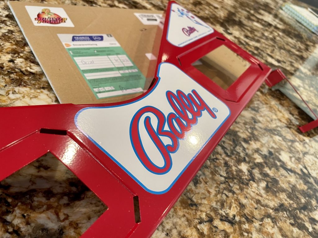
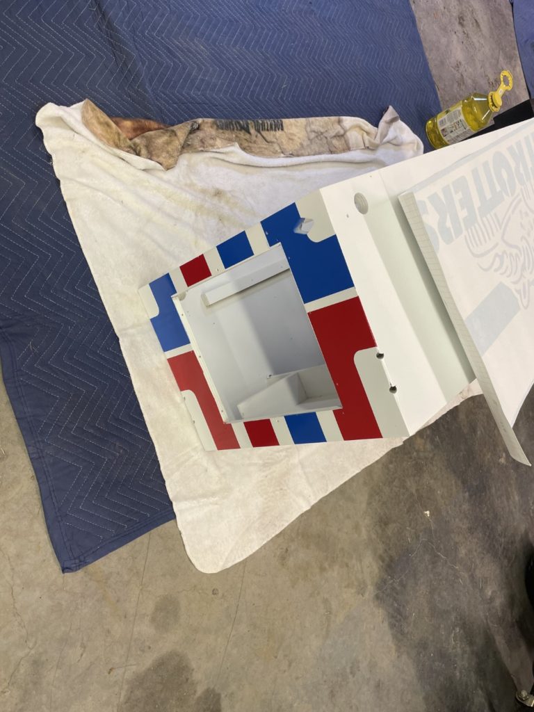
When we got back and in between the cookout and fireworks, I was able to focus on the apron. Mine did not look terrible. Very little corrosion, no big scratches, etc. But the paint was faded as were the logos (they are painted as well). Unfortunately, the red color on the apron is NOT best represented by “apple red”. Apple red is too bright – too much yellow in the mix. Another run to Home Depot had me coming back home with 2 more test colors: Regal Red, and Sunrise Red. A test spray showed that Sunrise was a close match.
Prepping the apron takes a bit of time. I worked carefully on it for at least an hour before painting it. The trick is to sand off the original painted logos WITHOUT sanding to the bare metal. You won’t find a better primer that the original paint on the apron (assuming that the original paint is still solid – no flaking/rust).
When sanding correctly with 220 grit, you’ll be left with a plain red apron, no artwork and very little bare metal. Once I had that done, It didn’t take long to get the red basecoat painted. It’s probably a good time to share with you my method for painting using the Rustoleum Painter’s Touch 2x spray paint. Lay down a heavy mist coat first. Wait for at least 60 seconds. Add your heavier coat next. I think this helps to keep the heavier coat from running. The first “mist” coat dries quite a bit in that first minute, the next heavier coat then combines with the initial one. It probably also helps with crinkling – where you are applying another coat on top of your original base coat.
While waiting for the cabinet paint to dry, I tackled another issue. The old power cord. It looked like it had been replaced at some point with an old lamp cord. To credit the guy that did the work – it did have a gorund plug and it was wired properly. The cord was old and out of character for the game so I ordered a replacement from Marco and soldered it on. It looks great and the black color IMHO is more appropriate to the game.
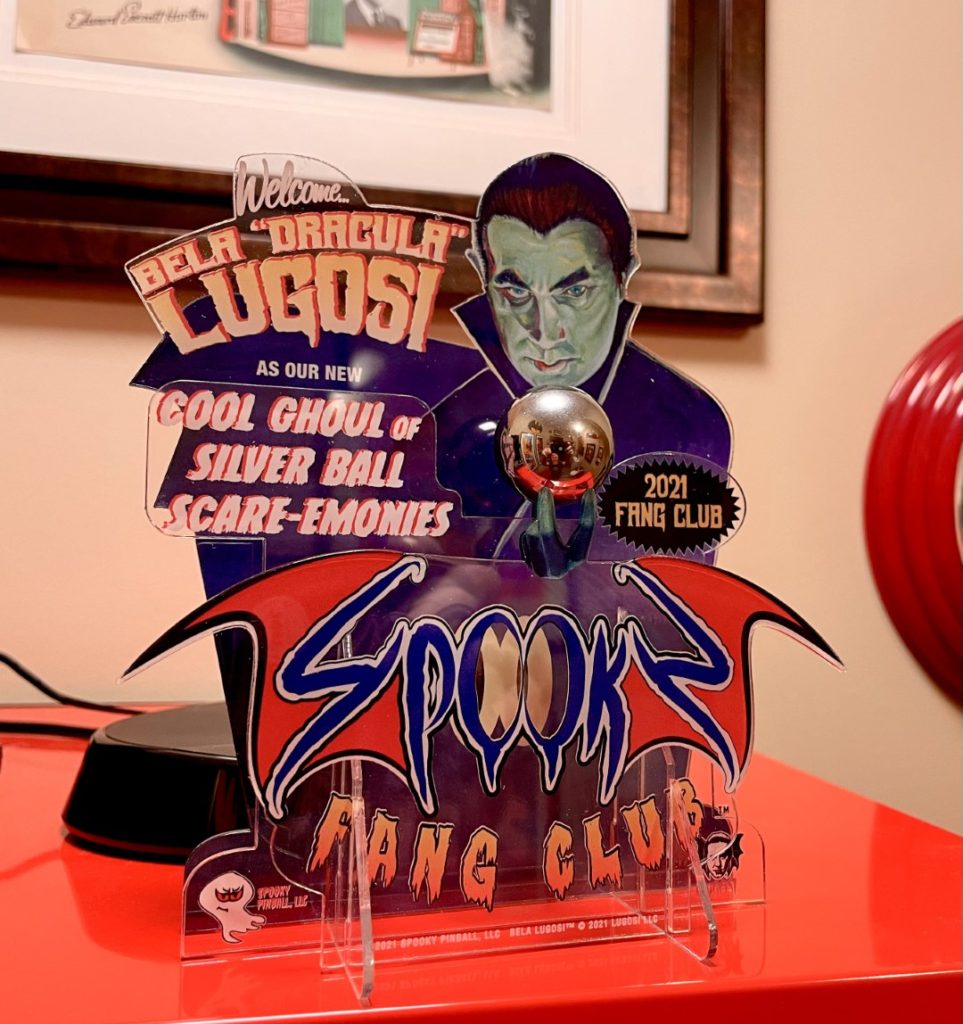
My birthday just happened to coincide with the release of Spooky Pinballs new title – Halloween. I did not care one bit. I have zero interest in horror. The game did, however look amazing and when they announced a sister title in Ultraman – I was excited and in for sure. I quickly joined the “Fang Club”, received my swag and “impatiently” waited for the day of the sale. I was in my office and had a window of 5 minutes set aside on the day it was released. At 1:00PM CDT the order banks opened and within 2 minutes I had secured Ultraman Kaiju Rumble #191 from my buddy Joe at Pinball Star. I know I won’t see if for a while but I’ll be busy with Harlem for a bit anyway.

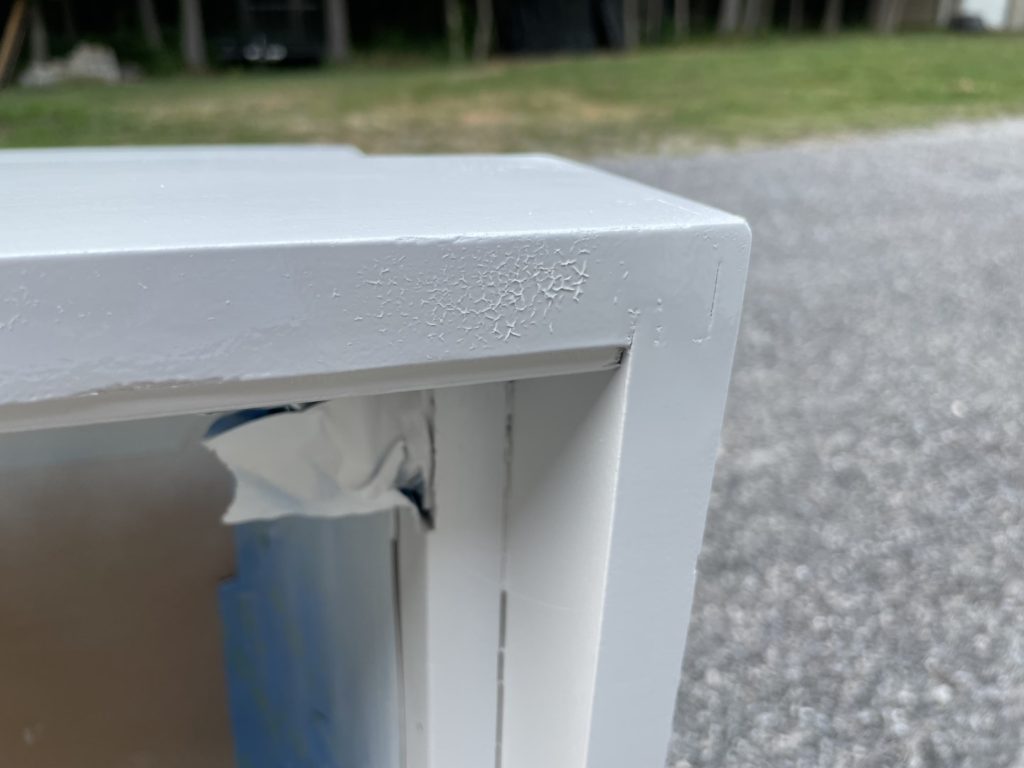
A day later, I checked to see if the primer on the head was dry and the first coat of 2x gloss white was cured as well. I had shot one coat of gloss white on the face edges of the head a few days earlier. All seemed good and ready to go. I grabbed the head, dragged it outside and sprayed a heavy coat of 2x gloss white on the head. I added another coat to the face edges that I had already painted a few days before. Big mistake. I noticed the paint started to move. It was crinkling and lifting/bunching. Not everywhere, but in about 4 places. Right in the spots where I had painted it days earlier. It was prevalent where I had added a heavier coat. Man was I angry. Too late to go back. I stopped spraying immediately and moved the head back to the pole barn to dry. By the time I had it back there, I noticed that 3 of the 4 areas had already laid back down flat. I was pleasantly surprised by that. There remained one small area on the corner that would need to be addressed later via sanding and touch up.
I popped back over to the house and spent a few minutes researching why the paint had reacted that way. The bottom line is that all spray paint has a high amount of solvents and if you don’t let each coat fully cure (takes days or sometimes a week+) then those solvents will eat into the older (uncured) coat and begin to dissolve/lift it. So my plans changed to making certain I left a full week between coats AND I painted only light coats and multiple coats 10 minutes or so apart. I waited a few more days to go back and address the cabinet base coat. The left side looked great, but the right side had some parts of the white that appeared more gray than white. If I had to guess, the paint was not as well shaken/mixed as it should have been when I sprayed it. This was the same side where I had a brand new can start “sputtering” about 15 seconds into it. This happened on the back of the head as well. Chalk it up to poor quality in manufacturing but it really makes a mess of your paint job. Far from “glossy” like it should be, the surface is dull and quite rough, with balls and flecks of paint almost sitting on the surface. I had to let it dry for 24 hours, then I used a 220 grit sanding block to knock down all the bumps that the specks of paint had formed. Tonight was the night to repair all that. Understanding ahead of time that “too much” paint, too soon would leave me with an even worse (crinkly) mess. I grabbed a fresh can of Gloss White and shot a medium coat and crossed my fingers. All went well. It dried glossy, looked great and did not wrinkly up. So far so good. While I was out there, I lightly sanded the crinkle area of the head (just a small spot remained) and shot a medium coat to cover the sanded area. That repair also came out looking great. One night – 2 wins!
A few days prior, I had sanded and sprayed the apron in prep for adding decals. It was Friday and Tami was out running an errand when I remembered the apron was probably cured and ready for decals. I grabbed it and the decals I had ordered a year prior from Ministry of Pinball. I trimmed out each decal to first work out the rough placement on the apron. Once sure of where they needed to land, I used a soapy water solution to lightly mist the apron, then place the decals. The water only allows you to remove, then reposition the decals if you get one side down and it looks incorrect. Once fully placed, there is no “sliding them around” so proceed carefully. All went well and I used a soft T-shirt to wipe the face of the decals and push any water remaining out from under them. Once completed, I took a few mins to add some mylar along the front edges of the apron where the ball connects “metal on metal” – this should reduce paint wear over time
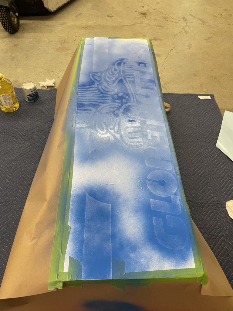
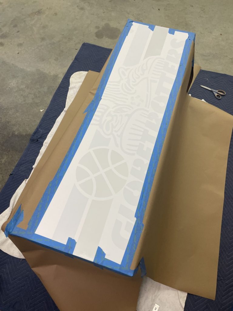
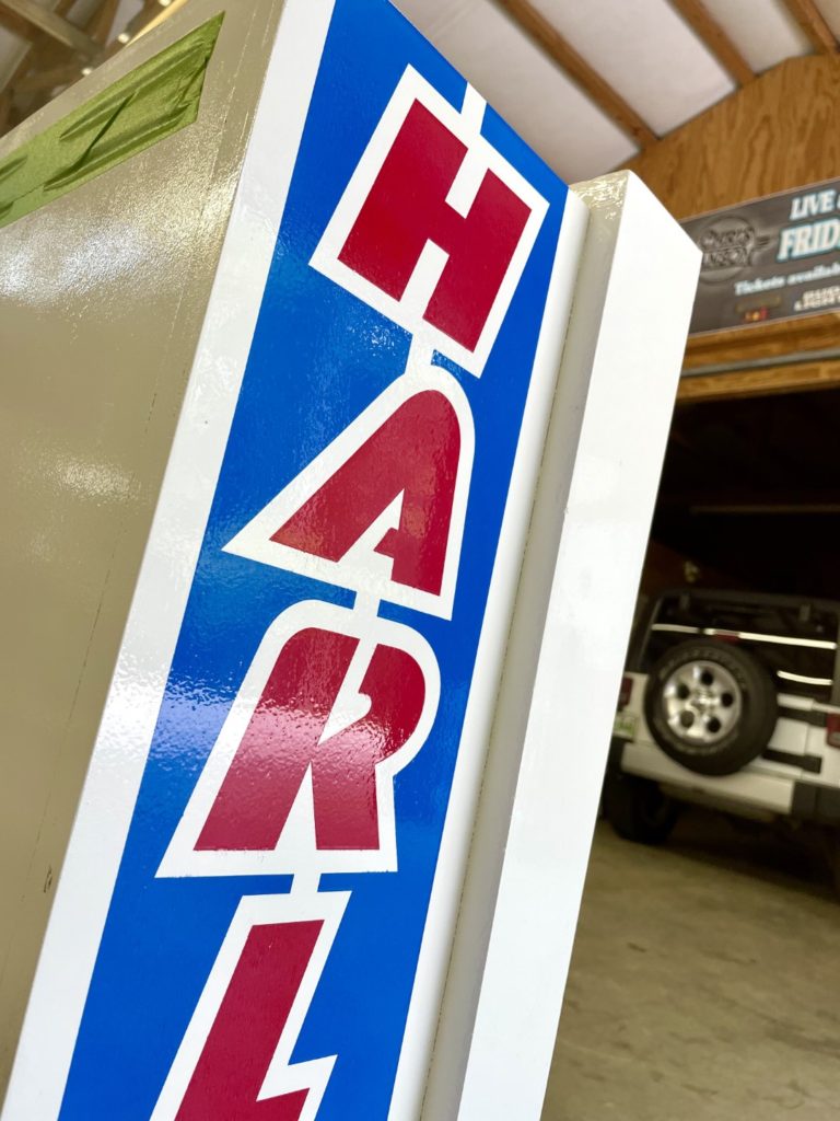
That same weekend, I decided I was not going to wait any longer. I was going to get some color down using my Pinball Pimp stencils. I decided to start with the head. It has a smaller surface area and is easiest to fix if I messed up. The Pinball Pimp decals have extensive instructions for the cabinet decals but the head stencils were more mysterious. I finally figured out they needed to be trimmed for Harlem at the “white stripe” locations. I trimmed them there and at the top and bottom. It was helpful to review an online picture of the original art before trimming. No biggie. I trimmed and then followed the instructions online at Pinball Pimp on how to install. Getting the stencil located, smoothed and then the masking removed was a breeze. Go slow and it will go well. I then carefully masked the remaining area I did not want to paint (or get overspray on) and grabbed a can of “Brilliant Blue”.
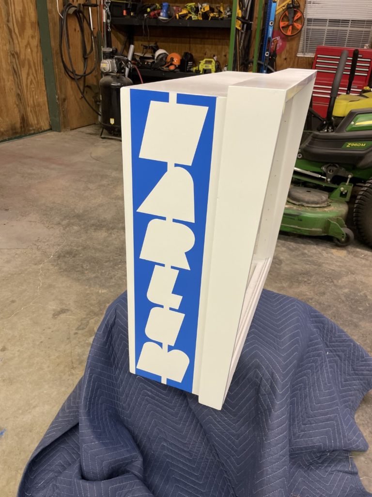
My process was: Light coat (still see 25% white showing through) … wait 3 mins. Medium coat (very little if any white showing through, could “live with it” as painted) … wait 5 mins. Light finish coat (just hit the thinner areas – use strong light to find spots with lower gloss) wait 2 mins and immediately start to pull masking materials. I pulled the outside masking first, then started on the stencil masking. It’s important to get your big pieces out of the way before you start the fairly finessed job of removing the stencil masking material. Like the video says, take your time and pull the material slowly and don’t allow it to break suddenly and drop into your fresh paint or touch an unpainted area. In the course of painting both sides of the head I had only minimal areas where the 2x paint was “sticky” or “stretchy” and would try to stay attached to the stencil mask and then “string out” slightly as pulled and leave paint stringers into the white (unpainted) area. These were always area that I had painted too heavily. None were so bad that if I just left them, they would not be acceptable BUT could have been avoided by laying down LESS paint. In every case, you’ll be better off with a little less paint!
Before the weekend was over, I masked off the neck area where the head mounts to give it one more fresh coat of Krylon black gloss. That poor area had seen quite a bit of overspray from the cabinet painting process and needed a touch up. It didnt take long to mask off the area and give it a shot of jet black Krylon.
Timing is everything now as I head into the home stretch and attempt to finish the cabinet art. The main cabinet is fully cured and I needed to get the blue laid down ASAP. The quicker I get that done, the quicker I can do the next color (red) and each color requires that I wait at least a week for full curing. I don’t want crinkling and I don’t need to be lifting the prior stencil color when I pull the stencil mask. With that in mind, I went out to the pole barn to get the blue stencil color on the front of the cab. Pinball Pimp tells you to start at the front when you have a “wrap around” design and it’s good advice. Makes it easier to match and place the side art when you have a defined registration point on the front. I cut the long stencil in half (both colors are on one sheet) and got it on the cab and sprayed successfully. When I was removing the mask, I noticed an entire area I had only lightly sprayed. i quickly taped it up and shot a final coat of blue – no harm done. Lesson learned there is to take a minute to visually inspect just before you spray to absolutely “know” where you are laying down paint vs the masking area – it’s not as obvious as it looks … especially when you are painting on a white base cabinet (the masking material is white too!).
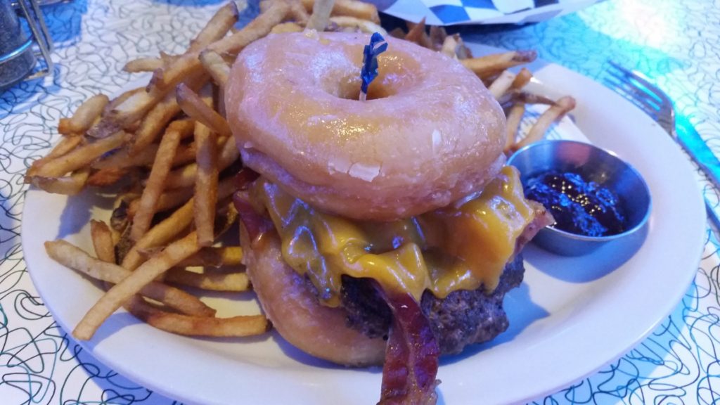
While I was waiting for someone to help me position the cabinet (read – lift it), I tackled the light panel hinge. It needed to be hand cleaned and them polished as it was covered in old sticker residue and years of grime. A few minutes with some Purple Power degreaser got rid of the grime, then a shot of Goo Gone removed the sticker residue. I followed that up with some metal polish. I also took the time to run each screw over the high speed buffer to really make them shine. Just takes a few secs but what a difference in looks. In short order the hinge was back on the head. It was a beautiful weekend so we all jumped into the Jeep to drive over to Hot Rods Diner in Maryville. 100 different kinds of burgers including on of my favorites – the Glazed Donut Burger (complete with grape jelly). Tami took a minute to pose for a picture outside.
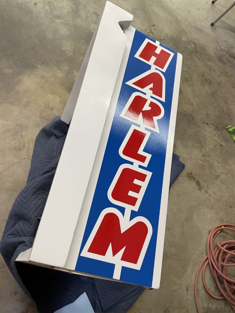
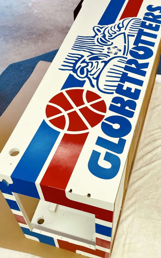
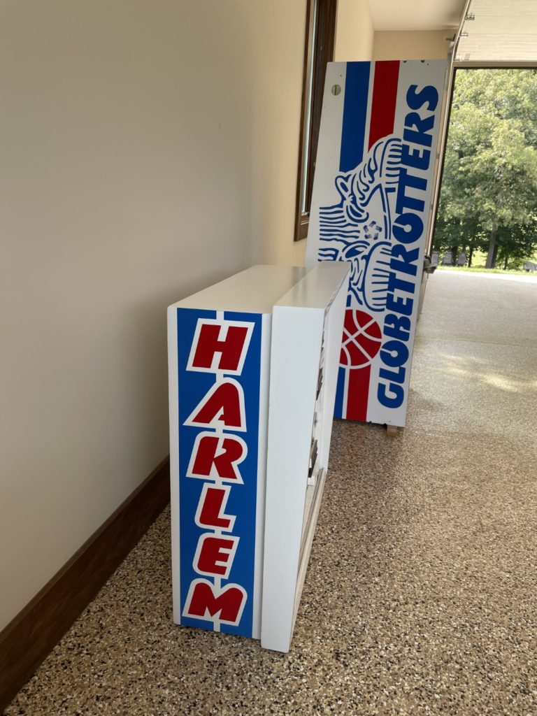
Well enough time had elapsed (a week) that I could now tackle the last color of my stencil set – the red. The red color was the easiest as it had less area and less detail than the blue (which included all the outlines of the basketball shoes, hands, globetrotter text, etc.). The red was a simple stripe and a slightly more complex basketball. Pinball pimp recommends starting with the front to ensure all wrap around stripes can be aligned. Before starting the red, I spent about an hour cleaning up some of the edges of the blue stencil on the right side where the paint had become stringy and then stretched out into the white basecoat. with the paint completely dry, I was able to use the point of a razor blade to gently scrape off the blue, leaving just the basecoat. It did a great job cleaning it up taking it from “acceptable” to very good and appealing to the eyes. Once complete with that, I did the front red stencil first and was careful to start my stencil at the bottom of the cabinet as I did with the blue. I let that dry overnight and then tackled the left side of the red. I dropped a piece of the stencil into the basketball when removing it (it’s easy to do even if you are careful) but the small mark it made was insignificant. I added a dot of red from the spray can and moved on. 2 days later, I flipped the cabinet and did the other side. That one went off without a hitch.
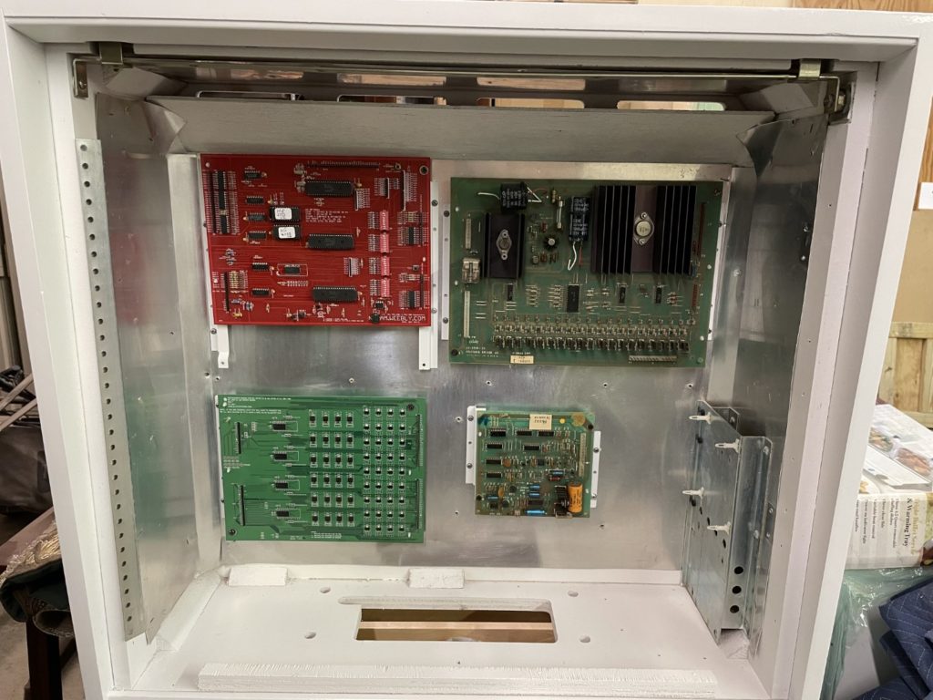
With the final colors/stencils completed, I had to wait a while to do the clear-coating. While waiting I decided to work on the backbox and a few other cabinet components. First step was to polish up the circuit board mounts. When that didn’t pan out, I painted them – primer white (and only on the face). The backside was left bare metal to provide a positive ground with the stapled in aluminum pan in the head, then each bolt corner (where I painted them) was cleanly sanded to allow for positive contact with the circuit board bolt and bare metal. The boards are mostly held on by the plastic standoffs, but the bolts on the corners provide grounding – no paint allowed. One of the front facing transformer brackets had broken (there are 4 total), so I “borrowed” one from the backside to replace it. Three brackets are more than enough to hold it. I mounted all the circuit board metal mounts into the backbox, then gently added all the circuit boards onto the brand new plastic standoffs that I bought from Pinball Life. Now I had to get the lightboard latches mounted so the door would stop swinging out wildly and scaring the pants off me!
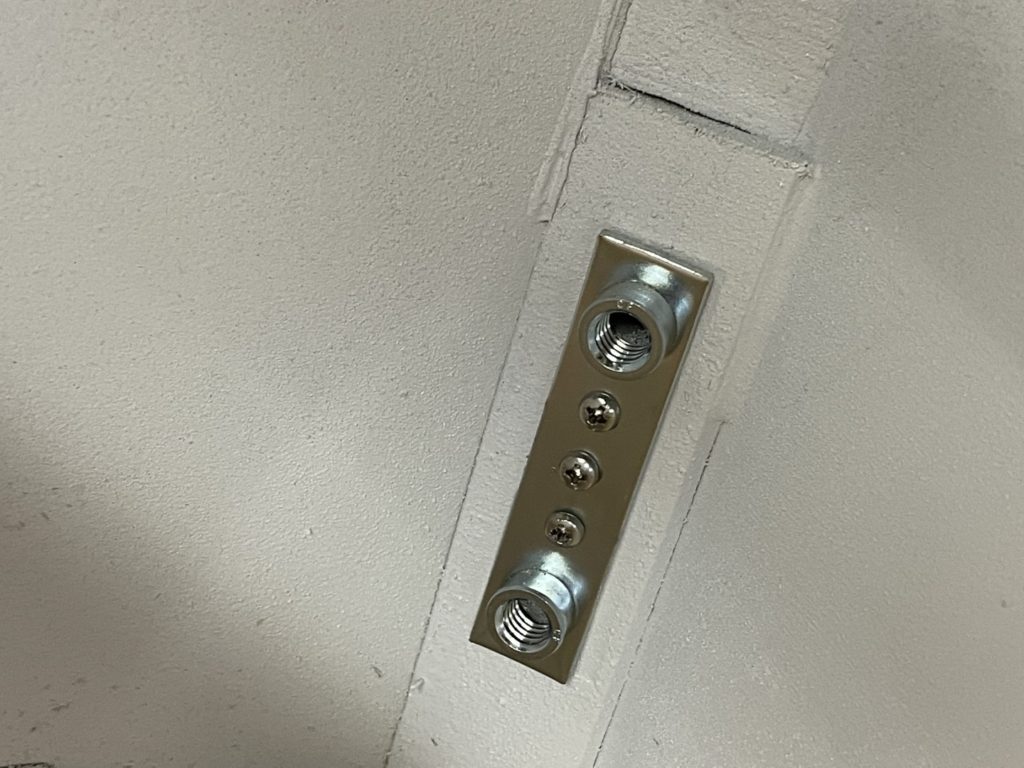
With the backbox sorted (for now). I moved on to the cabinet to get the new leg bolts mounts (interior) screwed into position. To get them “right” requires having a leg, the stern leg protector and the new mount in place all at once. Hold the new mount inside the cab while you gently tighten the leg bolts. When all is in the correct orientation and tight, you can then screw the interior placed bolt receiver into place (3 screws), then I loosened the leg bolts, marked where the Stern leg protector should be, and removed the entire leg, protector. Next up was to use those marks to mount the leg protector by drilling pilot holes and adding two screws. When all done, I removed all the leg protectors so they could be clear coated underneath

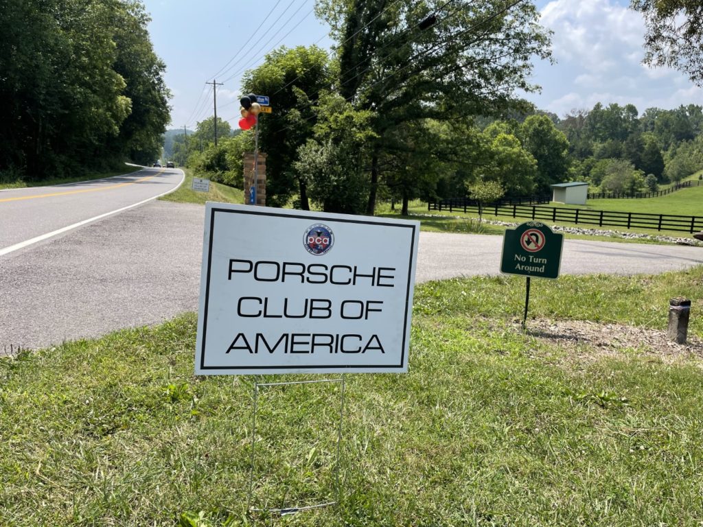
In between all of this restoration work, life was happening. We were preparing the ranch for 2 major events to be held at our ranch. The first being a PCA (Porsche Club of America) regional drive out and social and the second being my daughters October wedding. Central to each event was having the ranch in tip top shape beforehand. Sounds easy enough but in typical fashion we just had to complicate it. We decided to build a huge new pole barn/event center while getting ready. Over 30 feet wide and just over 50 feet long with a 15 foot tall ceiling deck. We were starting a new event business anyway, so the building would be used in the future for birthday parties, weddings, family re-unions, etc. The building would be the hub for all those activities and it would have a nice to have it “ready” for the PCA Social. Our family chain sawed down the large pines and a few small dogwoods in the area where the building would go – did that on a Sunday, in a lightning storm.
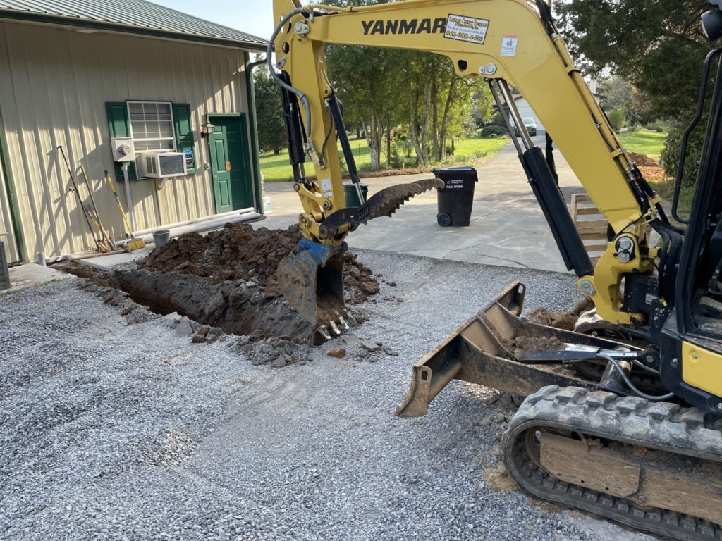
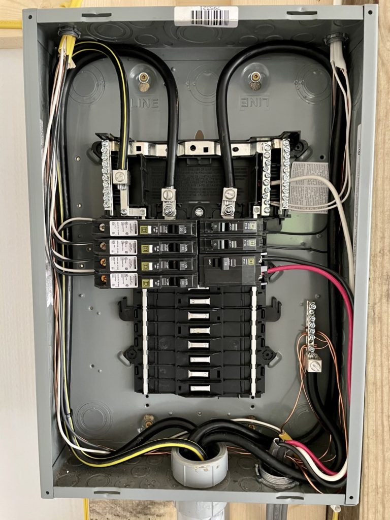
The following weekend we had over 20 truckloads of fill dirt hauled in and my daughter ran the steamroller to compact each load as it arrived. I helped a bit running the excavator and by Monday we had the space ready for concrete. 5 days and 40 yards of concrete later, it was poured and ready for a building. I paid to have a contractor build the structure BUT all of the interior work was mine … so, while getting the ranch ready for the July Porsche event, I had to wire the entire building (as in run the supply line and add a breaker box and then wire the building), install a full set of kitchen cupboards, hang a movie screen and projector and finish all the exterior landscaping. I had just about 4 weeks total to do it all in.
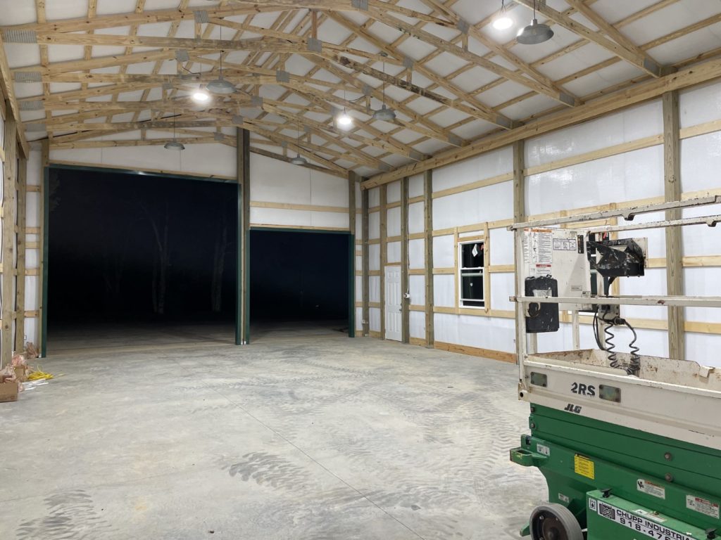
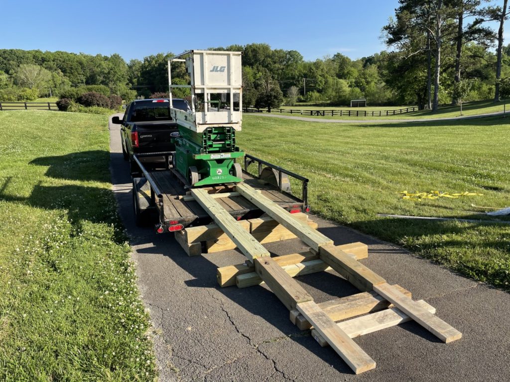
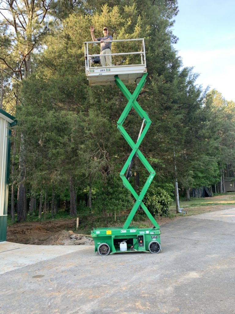
I rented an excavator to run the 1.0 gauge aluminum supply wire, mounted and wired up a new breaker box, added around 10 total circuits and ran 2 completely discrete lighting systems for the ceiling/open beams area – one with super bright LED warehouse lights (for working in there) and another separately wired set of galvanized “farm style” incandescent lights for weddings and social events. I even bought a used scissor lift to do all the work (godsend). The lift was so heavy (3,800 lbs) that it was bowing the steel supports on the bottom of my trailer. I spent 4 hours just building a ramp set to unload it. We finally got it safely on the pavement and into the new barn. Later, I bought a complete set of kitchen cupboards at Home Depot and in 2 days had all of them (with the countertop) installed.
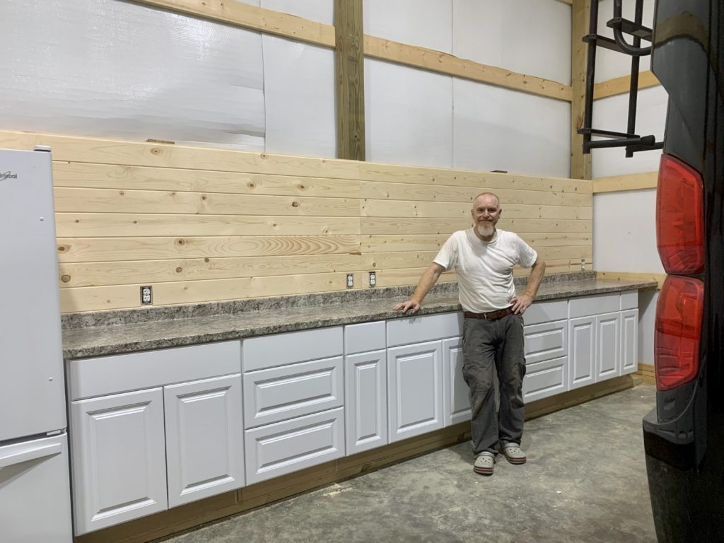
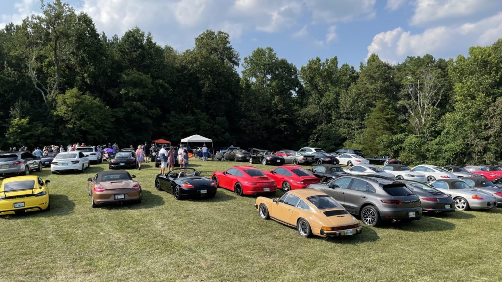
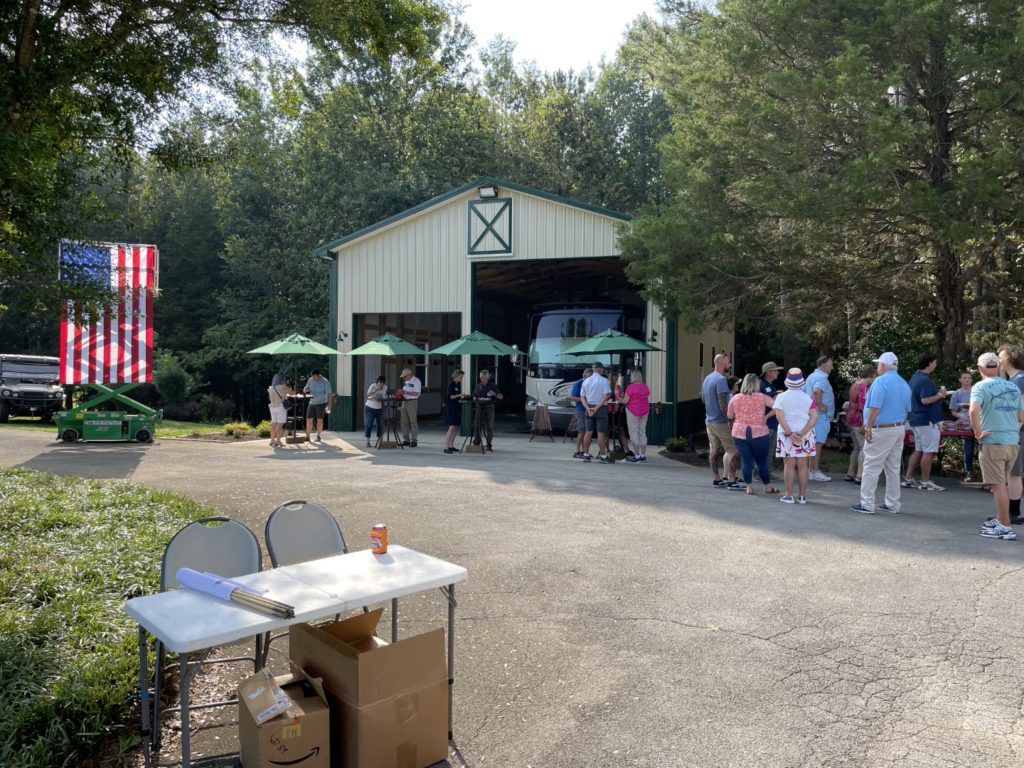
Tami found a nice used refrigerator to complete the install. The following evening Taylor and I installed the tongue and groove pine above it and the kitchen was done. I later added a motorized movie screen and an inexpensive 1080P projector and now our guests could have images playing during the wedding or family get together. Just ahead of the first event (PCA) I ordered 4 tall cocktail/umbrella tables to be used outside the new building. The event was a huge success. We had over $8 million dollars worth of Porsches parked on my NE facing hayfield, we had a band and tons of BBQ as well. Our members had fun as did we. Now back to that Harlem Globetrotters!


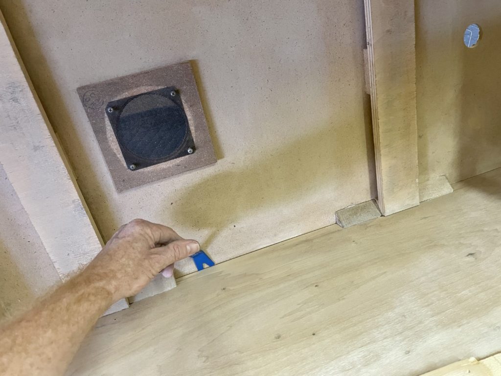
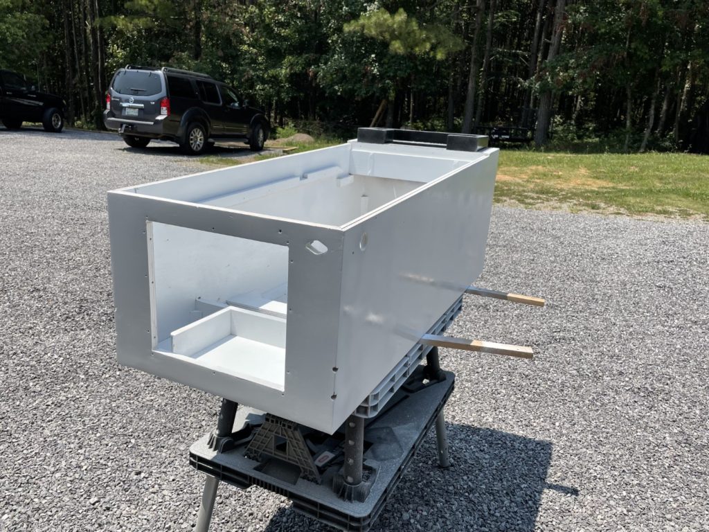
The club event slowed me down a bit, but literally the day after it ended I was able to move forward with the “last” and important part of the cabinet restore – the clear coat. I first installed the score displays that I had removed from the light board panel, the installed the light board. After that I taped up head (light board/face) to isolate it from exterior overspray. It seemed like it was also time to pull the tape and paper from base of cabinet and once that was done, I taped up cab interior to isolate it from exterior clear coat overspray. I was all prepared to use an electric sprayer that I had laying around. I have painted fences and our large gazebo with it in the past and it promised the convenience of electric power supply without the issue of potential water contamination that my compressor driven HVLP guns might have. No joy, however. I filled it up and attempted to prime it but it simply would not work. I had used it just 3 weeks prior and cleaned it before storing but something had clearly gone wrong. I left the Varathane in the gun and quickly grabbed and prepped one of my Harbor Freight HVLP guns (I used a new one so I needed to clean it from packing oils and add a water filter). I dialed in my compressor for 70 psi, donned my respirator mask and started to spray. I sprayed one medium coat, waited 2 hours and then sprayed another medium + coat. All went well … even better than I had expected.
The only issues I had were all “my fault”. On one side of the cabinet, I sprayed a bit too heavy and it (ever so slightly) started to run. I decided on the spot NOT to panic, and over the course of the next few hours watched those heavy areas start to flatten out to become almost invisible. You’d be hard pressed to find them now, just 48 hours later. The other area to watch for was finger prints, I had moved the head to a be clear coated and when I did, my fingers were dirty. I left 2 fingerprints on the back and then clear coated them into the finish. Oh well, got some DNA in there now. It’s not that bad, it’s on the back and I could touch it up but I won’t. Also, watch for any tiny overspray in your colors from your stencil job. I took about an hour to go over the cabinet with fine tooth comb looking for and fixing overspray spots. You can remove them carefully with an exacto knife. Remember, if you don’t remove them now they will get “locked in” by the clear coating.
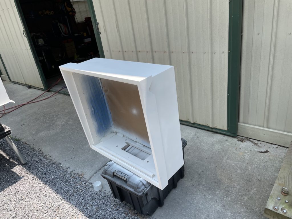
Today I moved the cabinet and head back to the garage below the Loft. No need to keep these freshly painted parts in the pole barn anymore. The work that follows will be assembly and I won’t be painting or sanding anymore. The 2 pieces sat in the garage for a day before I decided to haul them up to the Loft where it was cooler to do the final phases of the work.
I would have expected that the work ahead of me would be short and easy. I was wrong. The speed certainly picked up but the level of complexity and the number of “things to do” seemed to increase exponentially. In my mind, all I had left was: Get the cabinet wiring harness and ground braid in, get the coin door cleaned and in, solder on some new flipper switches and tweak some things on the playfield that I had not had a chance to finish. Yea – that’s about it, until you break down all that work and discover the coin door alone would be almost 10 hours of work! I got the cabinet and head moved upstairs and mounted the leg protectors and new chrome legs. I put some of those Harbor Freight tiny 3 wheeled dollies under each leg to facilitate moving the entire cabinet around as needed. That night I was able to knock out a few things. I mounted the speaker and the now highly polished playfield prop bar.
This week has been crazy with work and I’ve been getting home later and later so the work windows have been just a few hours a night. I’ve tried to set simple and small chunks of work that I know can be done in that amount of time. Early in the week, I printed out and organized all instruction cards for head. I printed these on bright white 65lb stock and they came out great. On Tuesday, I mounted the new polished chrome side rails using stainless screws. This sounds easy – right? Well not so fast. The holes DID line up, but each was off left or right by a 1/32″ or so. If you were NOT dealing with installing chrome – no biggie. My problem is that I was dealing with chrome.
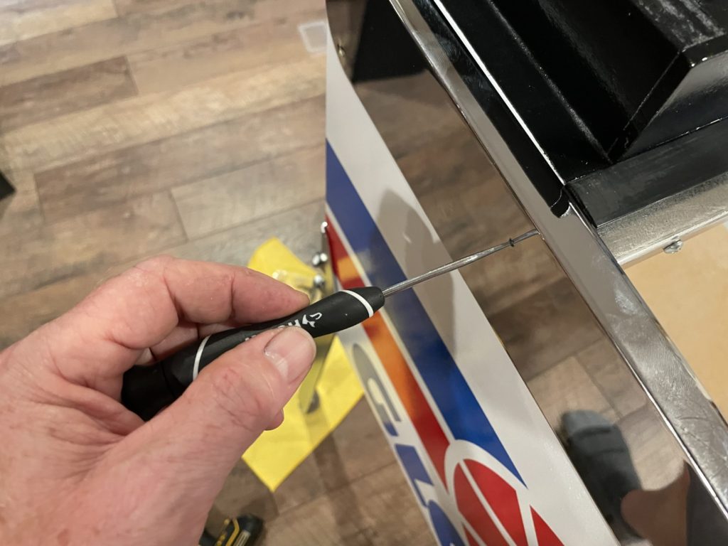
When you seat a nail or screw into the face of chrome material (especially relatively thin material) if the fastener is not perfectly perpendicular to the chrome surface, the edge of the fastener will hit the face of the chrome at an angle and put too much pressure in too small of a spot – causing a dent and visible distortion in the highly reflective surface. I used an awl to poke a new pilot hole, along with a fresh 1/16″ bit to make certain each screw was perpendicular. 75% of them needed this treatment. 2 hours later I was done with both side rails.
The following night I was planning on installing the ground braid that runs along the left side of the cabinet AND inside the head along the base. In fact, over the weekend, I had bought a Dewalt pancake compressor to do just that. I really did not want to haul my HUGE pole barn compressor over to the Loft. I already owned a pneumatic crown stapler and just needed a way of powering it. The Dewalt and the Meite MT-7116 stapler worked like a champ. Set them to 70lbs PSI and it worked perfect for both the ground braid and later for the operator/service cards.
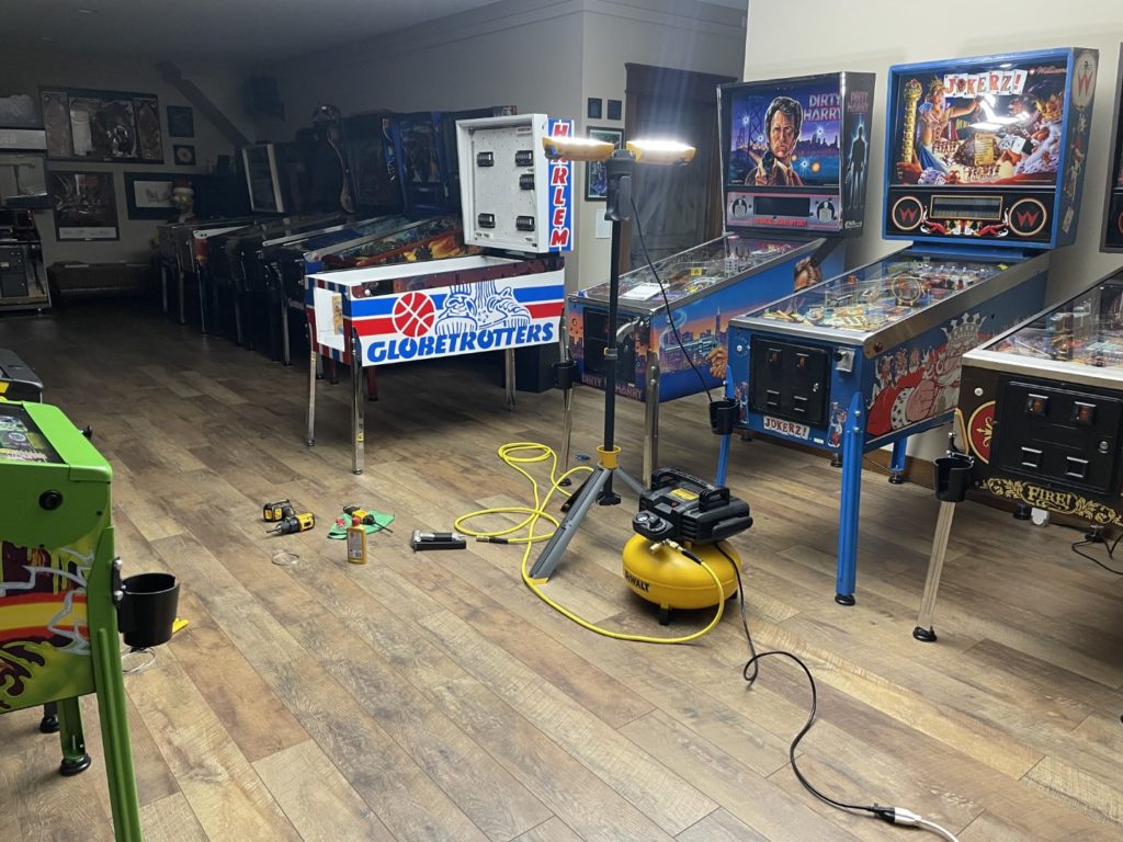
One trick I did to ensure that adding the ground braid would be easier later was to SAVE THE OLD ONES. I saved the length I pulled from the cabinet and heads and was able to create the right length from my new spool of braid AND was able to check it’s placement and routing according to my pictures as well. I ran the braid where I thought my pictures were telling me and (again according to the pictures) where it was supposed to end. When it showed that I was at the end according to the images AND I was physically holding the end of the braid, told me my routing was correct as well. It was a nice reassurance to place something that does not have a clearly specific mount hole/location like 99% of all other parts do. While I was at it, I added a quick disconnect to the cabinet braid where it traverses the neck into the head so in the future, it did not need to be cut (like it was when I purchased it).
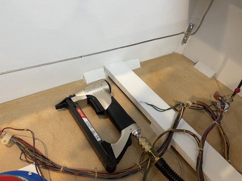
With the braid in, I could now mount the cabinet wire harness, varistor and power cord. These parts have mounting points directly on top of the braid to ensure solid grounding. Many if not most of the mounting points were still visible as the harness was mounted originally using retaining clips and wood screws. It was easy to re-install using these as a guide. The knocker and it’s associated plate is part of this and I re-mounted the pair at this time as well. The end of the wire harness nearest the players includes the main power switch accessible from under the cabinet. I had not cleaned the mounting plate or the switch area yet and I had to do that before passing the switch through the base of the cabinet and screwing it down.
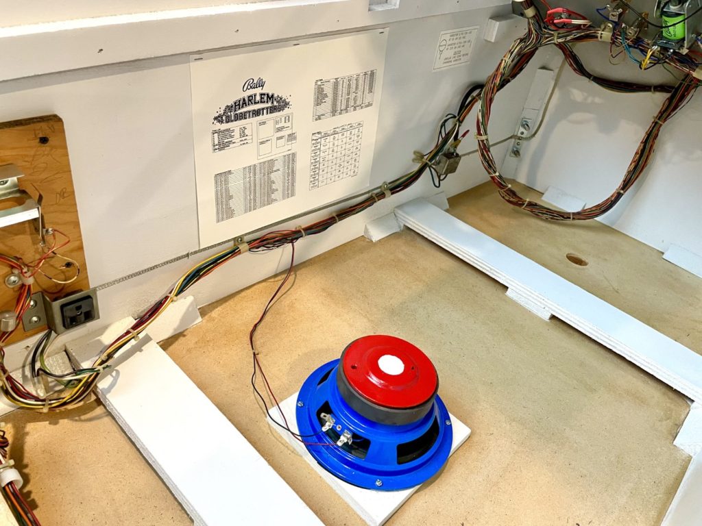
Finally, the old, beat-up and nearly worn out cabinet flipper switches needed to be replaced. I grabbed my soldering station and made quick work of getting them soldered onto the wire harness. I added fresh tubing to each of the positive legs to ensure voltage was kept “where it should be”. When the wire had cooled I tried to finish the job by mounting the new clear flipper button housings and the new blue flipper buttons but that part was a fail. Housings were perfect but the blue flipper buttons I ordered were for a more modern game so for now the button housings sit empty. I placed a quick order that evening for the correct replacements
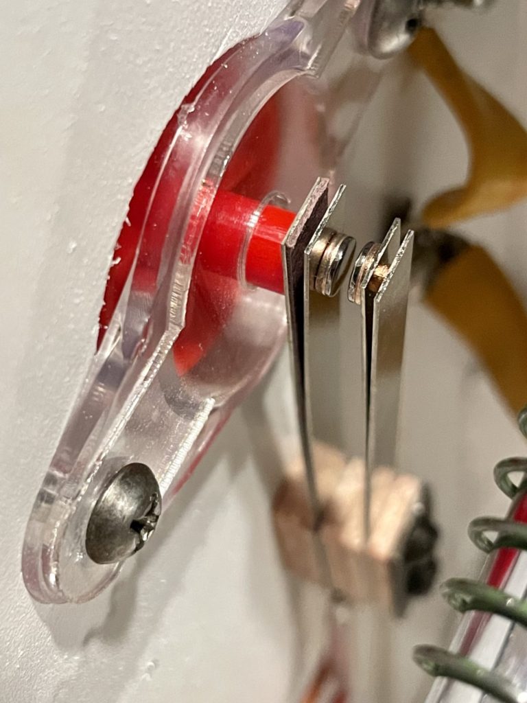
That effort went quickly and I had time to at least attempt to get my new backglass out of the box and the frame materials added. I dreaded the effort because I was unsure if the parts I had bought would fit my CPR reproduction BG. Well they did, and they fit perfectly. Something I had stressed over for days, was done in 2 minutes. In fact it took much longer to unpack the (well packaged) CPR glass than it did to get the frame parts installed! I was celebrating a bit when I walked the new BG over to the machine to install it.
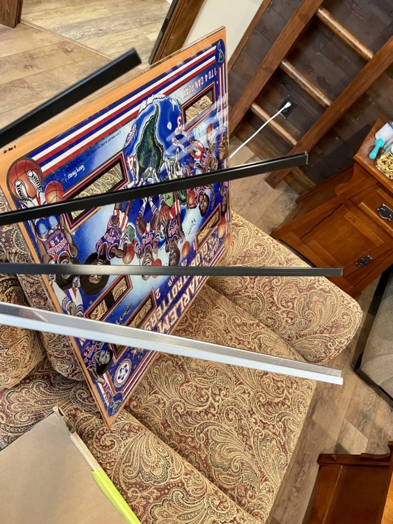
Once I got there I realized the head was in the locked position, followed by the “where the heck is the key” moment. That was followed by 2 hours of searching and trying to find and substitute “match” from the pile of keys I have here in the loft. No luck, I ordered a new one and removed the old one to have a safe haven for the BG until it arrived. How do you keep track of literally hundreds of unique parts for a machine for over a year – but then lose the key to the backbox??
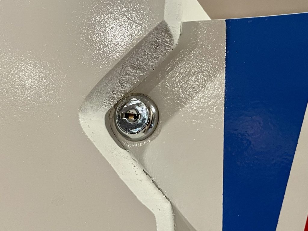
I had a few things to do to “finish up” the topside of the playfield. I set aside one night to do just that. Flipper, switches and spinners to be exact. I needed to mount the spinners because they are one of the playfield items that takes a topside and underside “look” to complete. I had purposefully left the switches that connect to the spinners “unmounted” knowing that the exact mounting position is determined by where exactly the spinning parts are located topside. Before I started I needed to locate the spinners, the frames and the connecting armatures. I found the first 2 right where they should have been (in my segmented parts trays I purchased specifically for this restore). I then spent over an hours searching for the “sure to be lost” armatures. As I was having a “here we go again” moment, I decided to look in the parts trays ONE more time (after looking 3x) and they were there all along – I had just missed them. These are not easily purchased either so I was glad I had them in hand. I carefully aligned each of the 3 spinner mechs before selecting, drilling and then mounting the associated below PF switches. After completion, they all spun freely and fast! One of the last but most critical things to do before dropping the playfield back into the game was to adjust all the switches. I added all 3 flipper bats first, then worked my way from those switches to the spinners I had just installed and finally, to each of the pop bumpers. It is nearly 100% easier to adjust leaf switches on a rotisserie than it is when the playfield is in the game!
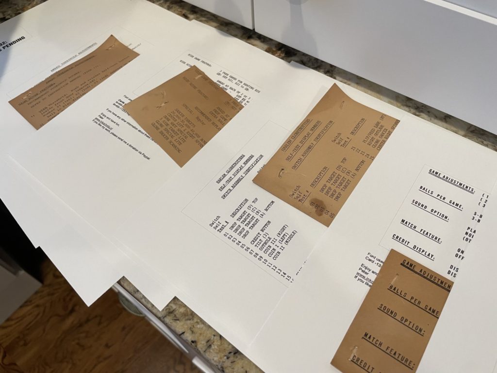
I got home late the following night and had just enough time to grab the old operator/service cards that I had pulled from the inside of the cabinet and head, compare them to the files I had found in the internet and then print them out on 65lb card stock paper. I printed the file, then carefully compared it to the original for both sizing and accuracy purposes. It’s easy to confuse them and although I thought this could be done a a couple of minutes, by the time I had them all printed, sorted, reviewed and trimmed, another 2 hours had slipped by. Getting them stapled in was a straightforward effort. I used my original pics and my new crown stapler to pop them back in the way I found them. This time though they were bright white and not “nicotine yellow”. The ones I added to the left and right side of the backbox were the easiest because you could still clearly see the original staple holes in the metal ground panel. The originals on the top panel of the backbox were not sized the same, but when I trimmed out my new printouts, I cut them the same height for a more uniform look. The only reproduction I could not find was the game patent certificate. It’s a tiny sign stapled on the cross bar behind the coin box and is unique to each game (has that game “name” on it) so I’m sure that’s why repros are not made. I scanned my slightly damaged original, fixed it up in Photoshop and printed a fresh one.
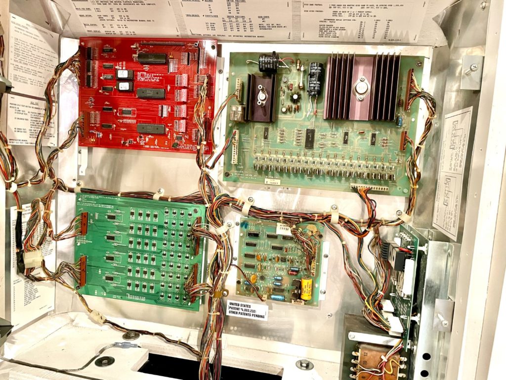
Next up was the most frustrating part of the restoration project. It ended well but man was it a challenge! The lock-down bar mechanism. Of all things to cause trouble. I noticed when I took it apart that it had a million small parts (washers, sleeves, screws, bolts, special inserts and more!) I took a few photos (not enough) then proceeded to mix all the parts up as I was going to Nashville to exchange some of them for fully chromed examples. Now I had all the chrome parts, and all the other (million) parts but no idea how it all “fit”. Holy cow … 30 mins of searching on the internet did not help much. No exploded technical drawings of a late 70’s Bally lock down bar assembly mech could be found. Look … for a Fine Arts major, I have an amazing sense of Engineering and Architecting skills. If I can see all the parts, I’m pretty sure that in a short time I can “figure it out”. Not today. This thing was baffling me. Finally I had the thought that some of my other games might have some similarities and I started poking my head in some late 70’s early 80’s coin doors. I struck pay dirt with the Bally/Williams “Truckstop” in my collection. A couple of hard to see cell phone pics later, I was off to the races in getting this assembly installed in the game (if more than 2 hours is racing …). If you’re wondering why on earth I would care about chrome in a spot virtually no one would see … easy, the original parts were rusted/corroded beyond belief (most are) and I simply did not want to spend the time trying to clean and then polish the mess. Chrome was like starting fresh and when I pull the glass in the future, the first thing you will notice is something that is rare as hens teeth – a perfectly clean lock down mech!
It’s the end of the week and I won’t be doing much work tonight. I got a message from Steve at Rock ‘n roll Pinball that he would be passing the ranch tonight and wondering if he and his son Braden might stop for a visit and some pinball. I was eager to take a break, meet some new folks and play so the answer was an easy “yes”. We had a great time, ordered a pile of pizza, talked more that we played and watched as Braden did an amazing job blowing up games like Aerosmith and X-Men. Braden was an Alabama State Champ and has placed in the top 3 on several occasions. Steve brought fresh cookies (secret recipe) that his wife made for me – that were to die for. They were headed toward Knoxville (Suttrees) to play in one of the first sanctioned tournaments since the COVID shutdown. We had a great night just enjoying the company, comparing notes no “who each of us knew in the industry/area” (answer is lots of the same folks!). We ended our visit just before midnight and had to run back upstairs for a photo op before they drove off.
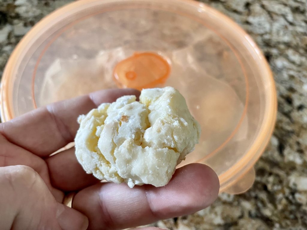
Decision time. I could have this game operational this weekend. I could call it done. I could move out the games I’m selling and pop this pristine Harlem Globetrotters on Tour in it’s proper place. Just ONE thing is standing in the way. The coin door. I need to decide. Many others have been at this crossroads too. If I chase “done”, I hang the coin door as it is and call it a day. If I chase perfection, I pull the entire coin door apart, bit by thousands of bits. I chose the later. Between Saturday and Sunday I disassembled the entire coin door down to the exterior skin. Every piece was removed to it’s most elemental component taking in excess of 6 hours. I learned a few things and you may benefit. I used tiny plastic zip lock bags to put each set of screws/hardware in – then labeled it with a sharpie. I also took 20+ pictures at varying angles to ensure I could rebuild it. Not everything got cleaned or polished the same. The coin door components condition varied widely. From “perfect – as new” to holy cow is there any metal under all that rust and corrosion.
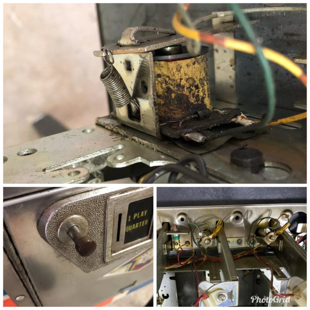
I used a high speed bench mounted buffer for the pieces that were the most corroded – after sanding off the corrosion by hand using 220 grit sandpaper. Lightly rusted (few spots) items got a touch up from the Dremel using a nylon buffing pad followed by red jewelers rouge and the cotton buffer head. Quite a few items went directly into the vibratory tumbler, then light polishing once out. The heavy backing plate (most of the mechs mount to it) that sits behind the skin had marks and scrapes AND did not look like it would polish well so I painted it using satin silver metallic primer/paint. The pieces near the top seemed to get more soda/beer/drinks damage than other parts and it showed in the bayonet bulb holders that light the coin windows. These were nasty so I soldered on a fresh set. When I was done with all the polishing, it was clear that the door skin was acceptable in appearance, but only acceptable. It might improve if I spent time re-graining the stainless but in the end it made more sense to spend the $100 on a new stainless skin from Marco. I placed the order that evening. Done would have to wait a few more days
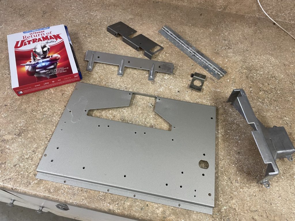
I still had a few more fairly complex items to work out before the coin door skin arrived. I had 9 or 10 yellow sleeved ground straps to attach, the coin door frame to install AND the shooter rod assembly. Sunday morning it was raining and it made for a good excuse to get it done. The coin door frame and the yellow ground straps are (unfortunately) a group proposition. Many of the yellow straps connect to the bolts that hold the frame pieces in place. So you end up doing all of it “at once”. This is another area I wish I had even more pics. Again, for the same reason as the ground braid … there is no “prompt” or drilled hole or obvious position where to place them. Without pics you’ll be guessing or searching the internet. I had most of the images but did need to search out images on the internet to confirm several others. The coin door frame was installed (drilled 11/32 holes to clean out) using the stove bolt kit (old bolts were not salvageable) I bought from Marco. I hand polished each of them (30 minutes) using my Dremel. They look fine as is, but are easily brought to a high luster using the Dremel and a cotton polishing pad.
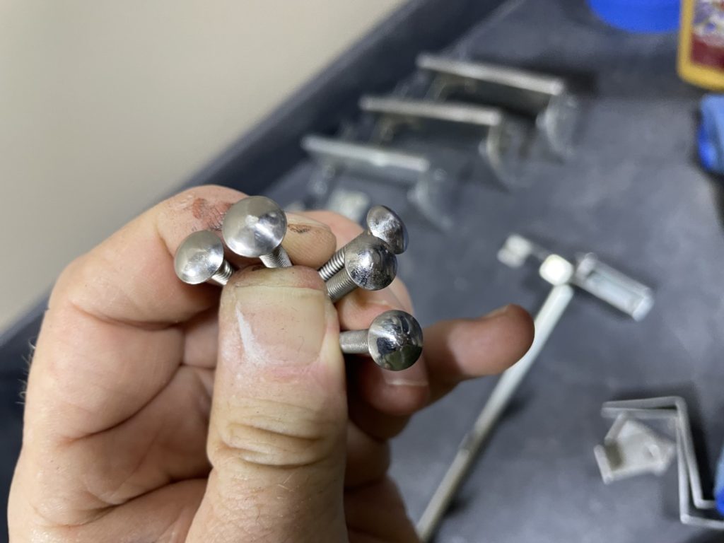
Drilling out the holes with an 11/32 bit makes the install a whole lot easier as it lets the bolt seat it’s square head into the frame easily so you can then carefully tighten but not over-tighten. The appropriate ground straps were added to the inside of the bolts before adding and tightening the supplied nuts. I then mounted the shooter rod/housing/spring assembly and tightened the two #10 nylock nuts but did NOT set the two wood screws. I wanted to get the playfield installed before making the final placement. The housing allows for large amount of vertical movement and I thought I would first pop the playfield in, and then check alignment before putting holes in the cabinet that might need to be moved. Being a Sunday, Tami asked if I would like a break to drive downtown for an early food truck dinner. I did. We did and we also popped into Cruze Farms for an ice cream treat. Vanilla waffle cone with sprinkles – killer. Taylor thought the spot I parked the new Jeep would make a great picture so she asked me to pose.
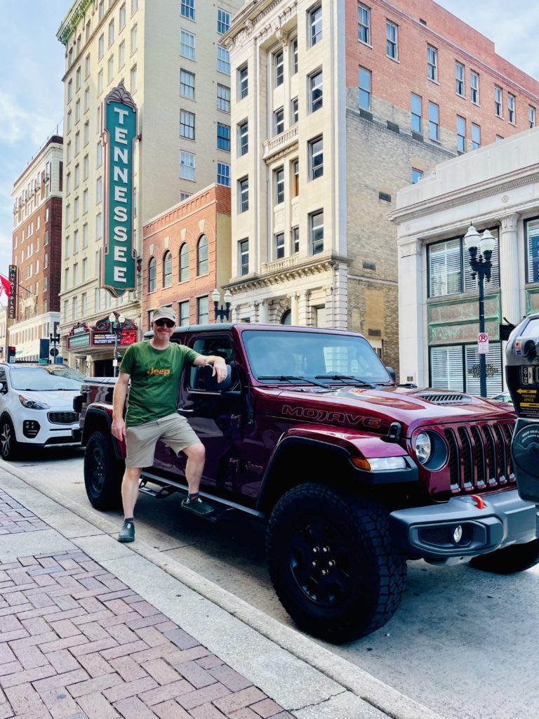
Getting close now – I can feel it! My first Marco order arrived tonight and I took a few minutes to install the correct flipper buttons (15 mins) and the rubber bumpers that fit under the top end of the glass channel. I had torn the retaining nibs off them when I tried to remove them to polish the cross bar they mount to. Finally, I had to install the new 1 1/8″ lock I ordered to replace the perfectly good lock that was already in the backbox (remember, I lost the key). I was worried when I opened the package for 2 reasons. The lock is very high quality and comes ready to configured in multiple ways – meaning it’s probably the best you will find out there. Secondly, the end (or tip) of the lock that fits into the cross bar that physically rotates was not nearly as long as the original. The original has about a 1/4″ square block of metal that fits into the square hole in the cross bar, that 1/4″ is long enough that it protrudes THROUGH the cross bar and is held on by a nut on the other side … the new lock had the same size square block BUT it was only maybe 1/6″ deep. I was concerned it was not long enough to properly engage the corresponding hole in the cross bar. I popped it in there, used the provided screw to firmly tighten it and voila – it worked. No slippage, nothing loose – it turned and functioned perfectly. Disaster averted.
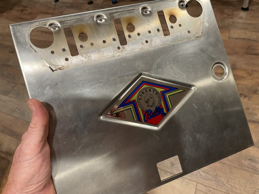
Tonight I prepared for the arrival of the new door skin. One of the items on the list was to get the playfield back in the cabinet. I added the 2 hangers (dimples were off by 1/8″). I added the apron “L” brackets and with some help from Chris, carefully lifted and set the playfield. It took less than 5 minutes to route the wire harness and get it plugged into the appropriate boards in the head. With that done, I flipped the power switch and watched as the machine sprung to life! At least the lights came on, the score displays lit up and nothing smelled like it was burning. It looked beautiful! I could not, of course, start a game as I was missing the entire coin door, but at least it was powered up and the lighting circuits I had hand soldered were correct. I had 2 bulbs out. One was a bad bulb and the other I had inadvertently left empty. I corrected that and moved on to putting together as much of the coin door as I could without the skin in hand.
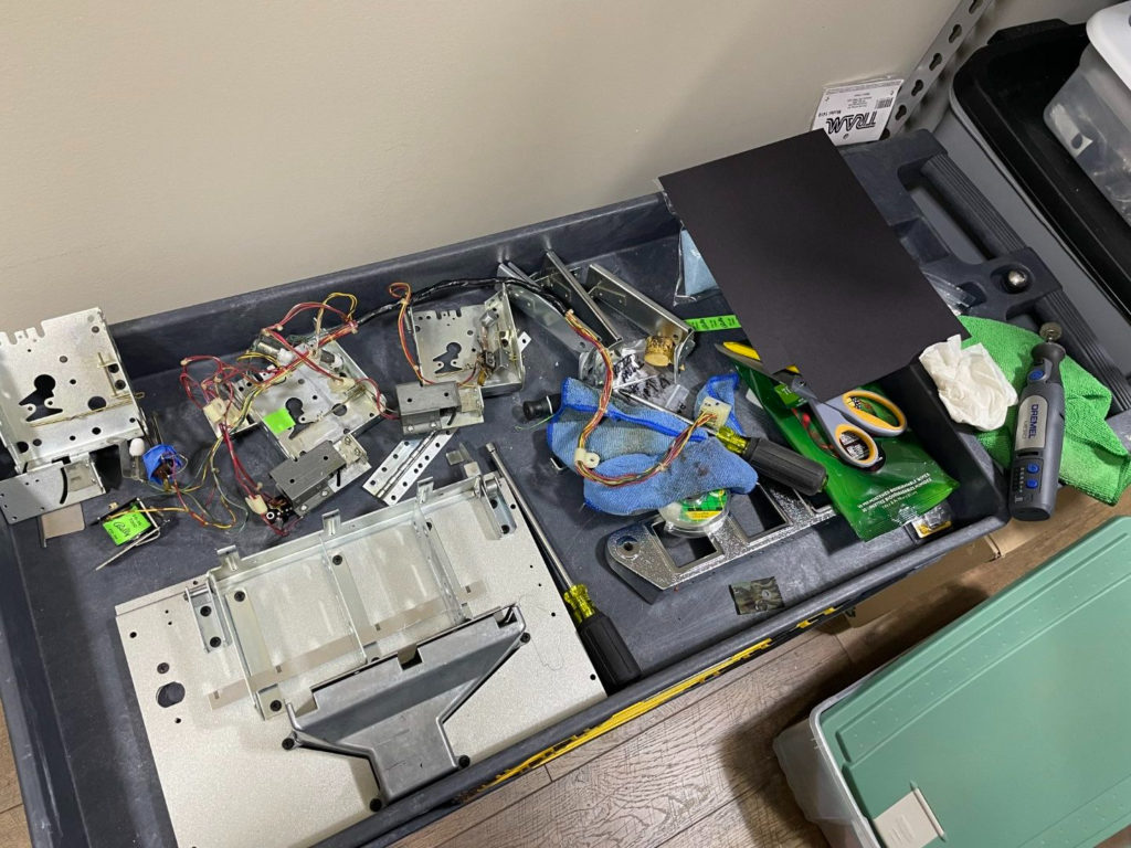
The coin door lay in a million pieces in the work room up in the loft. I was sure I only had maybe an hours worth of work to do. I was wrong. 3 hours later, I had taken the coin door as far as possible without the exterior skin. I mounted the bottom coin return chute, the perpendicular mech frames above it and the coin reject bar. Then it was on the cleaning up the remaining parts I had not addresses yet. I polished and cleaned: the small coni door coil and mount, the slam tilt switch, the start switch and all of the coin insert pieces (metal backer, plastic insert and stainless frame). The plastic coin inserts that denote game pricing required a heavy dose of Novus 2 to polish out the years of scratches. I finished by cleaning up the coin sensing switches that sit at the bottom of each coin slot/mech. There are 3 and all were taken apart to have their respective “box frame” cleaned and polished. When I was about to call it quits for the night, I noticed the 2 buttons that are part of the coin door front bezel. The coin reject button and the credit/start button. I wondered how exactly they connected and moved once installed. It was clear I was missing a few “C” clips (I grabbed them from my supply closet) and that at least the credit button was missing a sleeve that would be installed on the back side of the skin between the skin and the start switch. Not sure where it went or if there ever was one on this game, but I have a tray of plastic spacers of varying sizes and one that was close to the correct diameter (internal) to allow the button shaft to pass through. I Dremeled out the interior a bit and when done, had a brand new spacer that looked a lot like the drawing I found online.
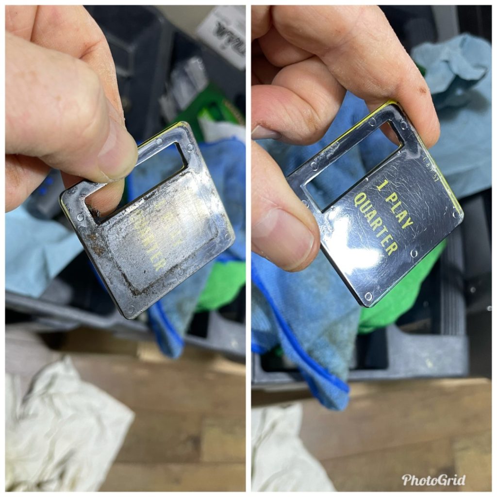
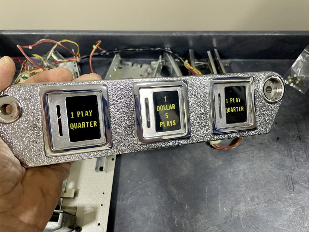
The last piece of the “put it all back together” puzzle arrived today – the coin door skin. It came from Marco safely protected in 3 layers of bubble wrap. I carefully, unwrapped it, then used the bubble wrap to lay it face down for the reassembly process. I’ll skip all the steps it takes to rebuild a Bally coin door, but you can find a great tutorial on Pinside (LINK HERE). My only struggles were getting my newly chromed coin bezel back on the smaller hinge that traverses the face of the door skin. I finally figured out that the hinge flap goes inside the bezel and that all the internal parts at each coin slot are captured (along with the hinge itself) by the black screws. Next, I learned that only ONE of the coin mech frames has tapped holes for the coin door coil, I had to move it to the farthest left-hand position but that took just a few minutes. Once I got that figured out, I had the door completely rebuilt in a little over an hour total.
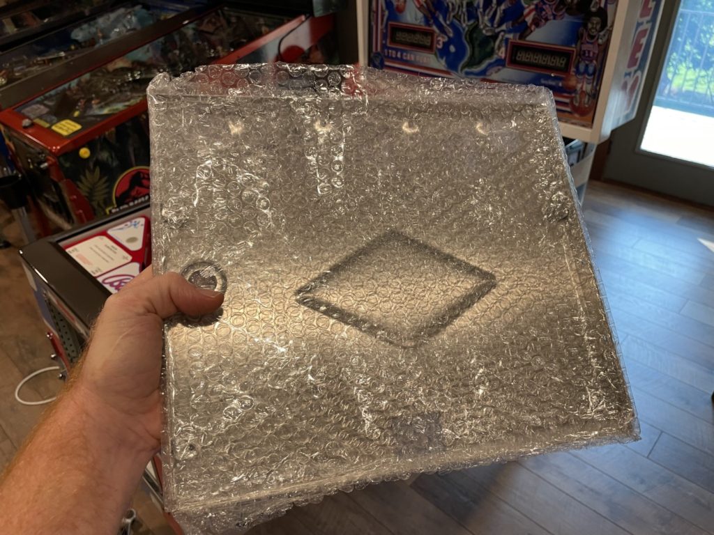
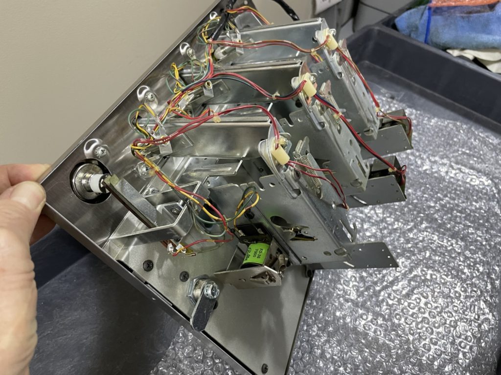
Hanging it was not as straightforward as I thought. The receiving holes (4) that are predrilled into the skin do not appear to be completely tapped. It took tremendous force to screw in each of the 4 screws that hold the door. They all went in, they seated and tightened well but wow – that was hard! I closed the coin door, wiped it down and admired the “newness” of it. It was beautiful. Time to light up the game and see what all these months of work have come to. I ran out to the pole barn to grab a fresh sheet of glass first as the game hadn’t had one installed in over a year. I slid the new glass in, moved the lever on the lock down bar, closed the coin door and flipped the power switch. It was quiet for a full 2 seconds but before I could “worry about it” … the game sprung to life! I got displays, GI and sound. This was good. I then re-opened the coin door and flicked one of the coin switches to add credits – that worked too. I’m on a roll. I pushed the start button and the ball popped nicely into the shooter lane … still all good. I plunged the ball with a huge smile on my face and started a game. The ball raced toward the right flipper – I flipped it right through the left spinner. As it made it’s way toward the left flipper, I punched the button and the game went dead. Ugh.
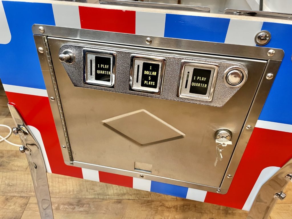
Harlem – Conclusion
To be honest, I was not really that disappointed. I know how these things go. I was expecting bigger problems and even earlier in the boot up sequence. The good news was I was fairly certain where the issue was. I flipped and it quit – so I needed to start the search there. I popped open the backbox and quickly found the F6 fuse blown. I replaced it, then lifted the PF to check out the left flipper wiring. What had I done wrong? I was so very careful in my notes and pics to solder back the wiring in the same order. I pulled out my phone and reviewed the images of the original wiring and compared it to what was in front of me. Sure enough, I had moved one wire on the lower left flipper (the one with the complex dual action switch) to the wrong lug. I unsoldered and moved it, powered the machine back up and it worked like a charm again. Problem solved. The other gremlins that presented themselves were small in nature but it took a few evenings to get them all ironed out. I won’t write about them but rather list them below:
- The spinners had no sound (might have been related to below)
- The slam/tilt switch on the coin door was touching the coin door
- 2 insert bulbs were out on initial power up (one bad bulb, one missing entirely)
- None of the pop bumpers had lights (there were no bulbs in them – I remembered worrying about how little room there was to fit a bulb in there so I never added them)
- The right sling was machine gunning (pulled the switches and re-gapped them)
- The top of PF left switch behind the rubber was forced closed by that rubber and not registering (pulled switch and re-gapped)
- The left outlane ball gate had a loudly buzzing (coil was not tight enough contact to the mech armature)
- I needed to add 2 wood screws to the plunger rod now that I knew it was correctly located and functioning well
- I had to raise the inline drop targets about a millimeter or so, they were a bit too low and occassionaly causing a stuck ball in the PF openings
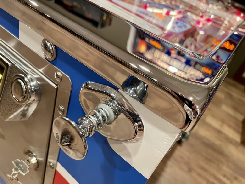
As I was closing out the last minor issues with the game, I remembered that I had a few Globetrotter memorabilia items I had stored away for this moment. I purchased an original (unused) HGT ticket from a 1979 show in Oregon and I also got my hands on the original Bally mechanical drawing of the basketball spinner used in the game. It’s done in hand drawn pencil on typical blueprint parchment and dated from 1979. What an amazing piece of history. The ticket and the blueprint will be framed together and hung in the loft near the game as a reminder of the Globetrotter team the game represents and the great folks at Bally that created it. Speaking of the creators, it’s probably a good point to share those details:
- Harlem Globetrotters on Tour
- Bally Manufacturing – Manufacturer
- 14,550 games produced
- September 1979 release
- Greg Kmiec – Game Design (Paragon, Xenon, Bobby Orr)
- Greg Frerres – Game Artwork (Kiss, Scared Stiff, Medieval Madness)
- Cool game facts and trivia:
- A white splotch of paint in the artwork on the backglass was added by Greg Frerres to represent the terrible Chicago winter of 1979
- There are 3 world landmarks in the art: Big Ben, the Eiffle Tower and the Stature of Liberty
- Greg Kmiec adds a single, unique “red post” to all of his games – find it at the left spinner on this one
- Sweet Georgia Brown is the HGT theme song and it plays at the beginning of each game
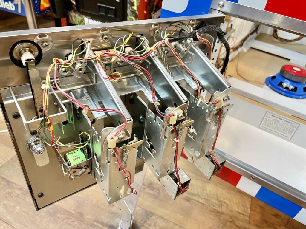
The game as it sits now is breathtaking to me. The impact of all that chrome, the whiteness of the new cabinet paint, the vividness of the freshly painted red in the stencils gives me sensory overload. Everything is crisp, fresh and square. I guess it’s easy to dismiss all of the little dings and grievances that happen to a routed game – I’ve got plenty of them in my collection but I seem to “overlook” the warts. The restored Harlem screams – “look at me, I’m perfect” and when I do, the view is proof that it’s true. I want to look at it more than I want to play it (and I love the game).
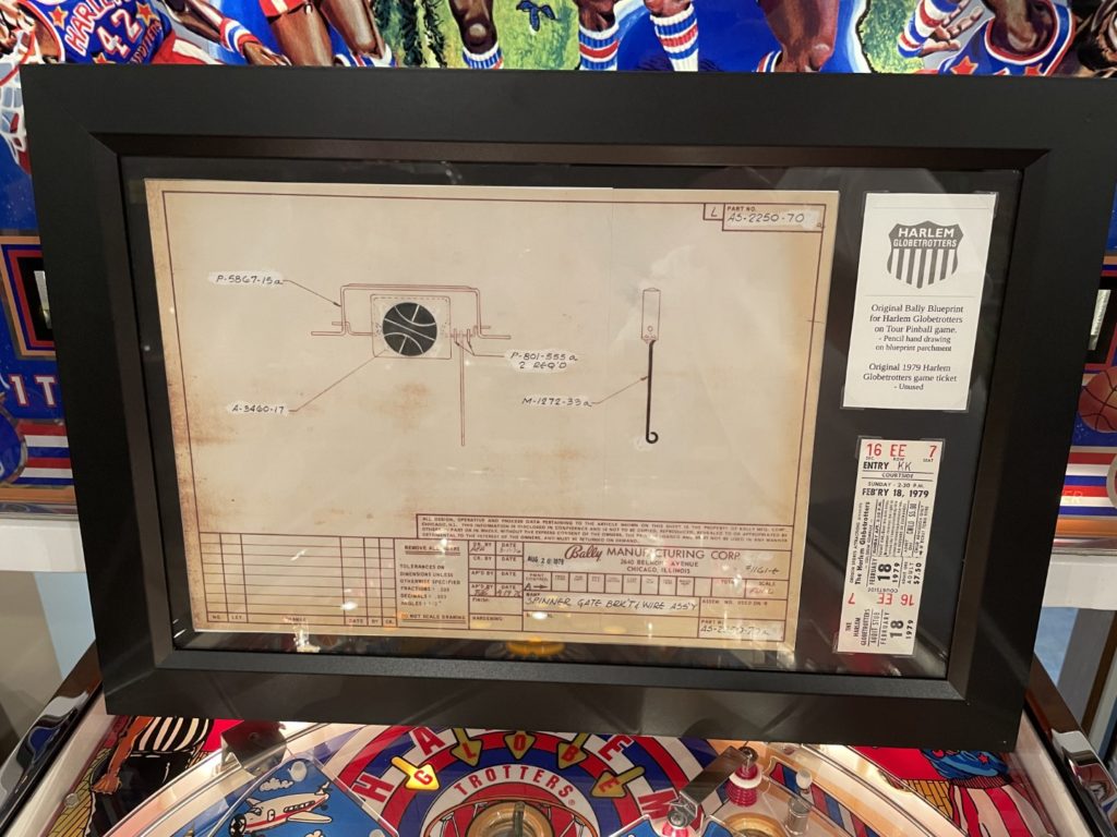
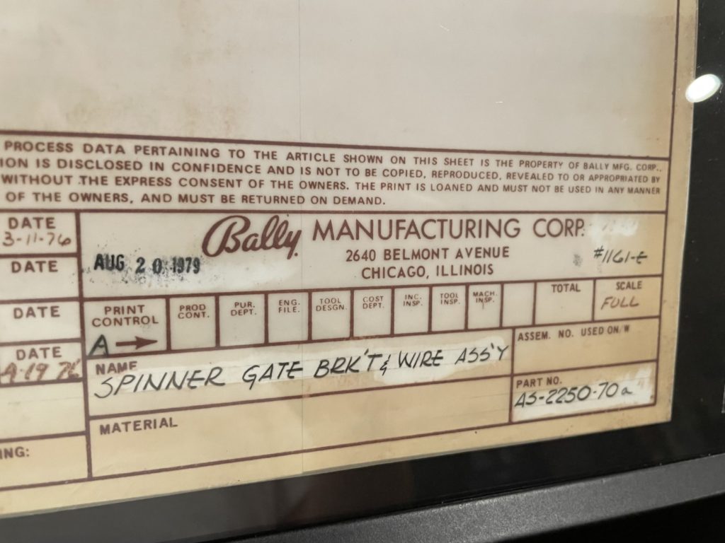
There are areas or parts of the game that are the even more remarkable to me than others. No, it’s not the chrome. First it’s the area under the lock down bar – the wood edge of the cabinet and the lock down mech itself. They are pristine. Having pulled the glass and lifted playfields on other games hundreds of times, that “clean view” is jarring. This is always one of the nastiest spots on a game. Coke, beer, rust and other dirt and grime seem to gather here all gently guided to this landing spot by the glass acting as a runway. The same can be said for the coin door. I turn the key, swing it open and just stare at it in disbelief at a 40 year old game with a coin door free of rust and drink stains. It’s a little unreal but beautiful to behold.
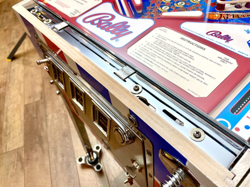
Final Comments
I feel like I’ve climbed my “Mt. Everest”. I looked at the first photo I took of the game the day I bought it. That date was May 19th 2019. I looked again at the very first photo I took the day I prepared to tear it down for restoration – oddly enough it was May 19th 2020. One year to the exact day after I bought it. Fast forward to today, August 5th 2021 and it’s finally complete. This was the most extensive restoration I have ever done. I’ve never taken a game and literally rebuilt it to “better than new”. It worked. It’s done. I can also say it’s done the way I envisioned it to be. No shortcuts. I remember staring at the dirty/rusty/corroded coin door thinking how easy if would be (it was the last item needed to complete the game) to just “bolt it on” and call it done. Instead, I gave it the same level of effort I gave the other parts of the machine and 12 hours later it was “really done”.
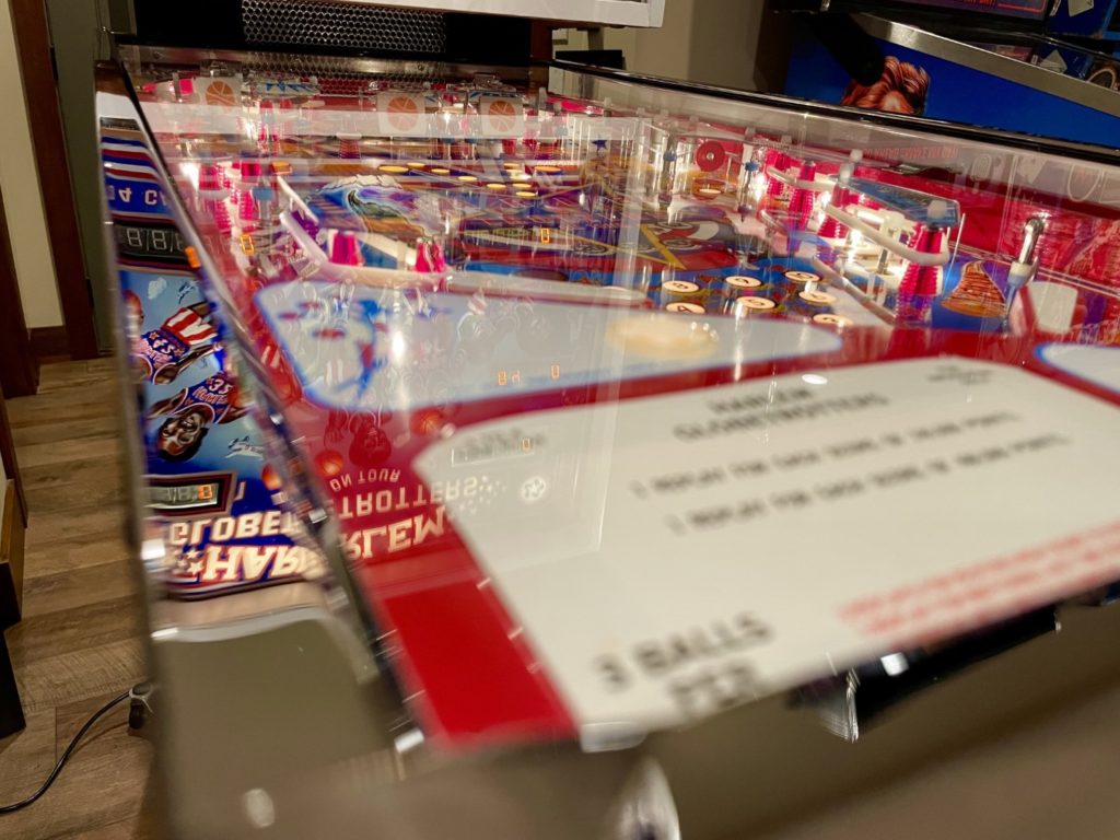
The restore took Intense and intentional effort that resulted in a cabinet sanded to bare wood, new parts added where needed and existing parts brought to function “as new”. The outcome is something I’m proud of. I never doubted if I “could” do this, but I had plenty of days where I wondered if I “would” see it through. Restoring a Pinball machine is a real test of anyone’s ability to focus over time. To start something that you won’t get done in a week or so. To begin work that will require ongoing effort, stamina and problem solving. If that is a challenge for you (isn’t it for all of us?) then “doing it” – and making it to the end feels amazing. From the beginning to end a total of over 2 years have passed.
The work came in a series of intense sections of weeks around the summer of 2020 and then again this spring/summer of 2021. Along the way, I took one of the 14,550 original Harlem Globetrotters on Tour Pinball machines and made it as special as the day it came off the factory line. My hope is that as others get a chance to play it, they remember with fondness the Meadowlark Lemon days of the Globetrotters. I hope they recall how much fun it was to see the team live during that time. We laughed at their silliness and were awed by the demonstrations of basketball skill. That’s not nostalgia talking, it’s just the way it was. Pure – simple – fun, with no agenda. Just fun. We all need a bit more of that in our lives

About the Globetrotters:
The Harlem Globetrotters embody a similar theme as I wrote above in closing this blog. The ideas of: sticking to it … the long haul …ongoing effort and focusing over time. They started the team way back in 1926 as the “Savoy Big 5” and were formed to act as entertainment before scheduled dances at the Savoy Ballroom. Many famous basketball players have played for the Globetrotters since then. Greats such as “Wee” Willie Gardner, Connie “The Hawk” Hawkins, Wilt “The Stilt” Chamberlain, and Nat “Sweetwater” Clifton later joined the NBA. The Globetrotters signed their first female player, Olympic gold medalist Lynette Woodard, in 1985. Baseball Hall of Famers Ernie Banks, Bob Gibson, and Ferguson Jenkins also played for the team at one time or another. 95 years have passed since the teams founding by Abe Saperstein and since then they have played more than 26,000 exhibition games in 124 countries. The team is still touring and still sharing their style of fun at over 450 live events worldwide each year.
Epilogue: I ordered and installed a new sound board (NVRAM/Weebly). The existing one functioned but was noisy and was picking up the sound of the lamps pulsing and a bit of transformer hum. The new one is dead quiet and the sounds coming from it are significantly better/clearer. I also ordered a playfield protector from my friends in Germany. No need to put ball marks on my CPR silver.
Useful Notes:
Harlem Paint
- Rustoleum 2x gloss white
- Rustoleum 2x gloss brilliant blue
- Rustoleum 2x gloss Apple red (cabinet)
- Rustoleum 2x gloss Sunrise Red (playfield apron)
Harlem Spend
- Machine $2,000
- Pinball Life $474 (playfield parts)
- Pinball Life $175 (rails, pop parts)
- Pinball Life $75 (legs and posts)
- CPR $650 (new playfield)
- CPR $100 (new plastics)
- CPR $300 (new back glass)
- Marco $100 (ball shooter rod, Star posts)
- Marco $70 (springs, cab switches, shooter bushing)
- Marco $100 (door skin)
- Ministry of Pinball $50 (apron decals)
- Pinball Pimp $150
- Titan Pinball $50
- Jameco Wiring $50
- Lee Valley (drill bits) $75
- PPS $48 Bally BG lift channel
- Staples $100 (special green paper for coils)
- Molotow Paint $75
- Pinball Restore $50 ground braid
- Hot Rod Plating $1,000 for chrome parts
- Home Depot $150 Sandpaper, bondo, paint, primer, respirator filters, masking paper, etc.
- NVRAM/Weebly replacement sound board $100
- Playfield Protector $150
- ALL IN COST = $6,000 (not including my time)
Above costs do not include critical tools needed to complete the work: Compressor, pneumatic stapler, drills, HVLP gun, Dremel, bar clamps, cutoff grinder, and many other various hand tools
Harlem Wire Codes & Notes
Last 8 harness retainers are mounted flat to PF (no stand offs)
All the rest have 7/16” gray stand offs
Drop targets:
T1 front blade (away from frame body), then closest
T1 white and green 2x
T1 white and red 2x
T2 white and brown
T2 jumpers from T1 (white and red)
T3 white and orange 2x
T3 jumpers from T2 (white and red)
T4 white and black 2x
Coil diode side yellow 2x
Coil other side red and black
Insert bulbs:
1 orange and black dash
2 red and green
3 green and green
4 tan and gray
5 red and blue
6 gray and white
7 brown and orange
8 white and green
9 darkened light blue
10 dark blue and orange
11 dark green and white
12 white and brown
13 dark green and white 2x wires (same color as #11)
14 dark blue and orange 2x wires (Same color as #10)
15 darkened light blue 2x wires (same color as #9)
16 white and green 2x wires (same color as #8)
17 white and yellow
18 red and yellow
19 blue and yellow
20 gray and black
21 black or purple and burgundy
22 white
23 green and black
24 yellow
25 gray and red
26 gray
27 red and blue
28 dark blue and yellow
29 dark blue or black
30 brown
31 gray/brown and burgundy
32 white and red
33 green and yellow
34 white and brown
35 light green and white
36 red and white
37 pale blue and white (has darkened to a green)
38 purple or black and green
39 orange and purple
40 light brown and red
41 white and yellow
42 gray and brown
43 yellow and white
44 black and white
45 gray and red
46 purple or black and yellow
47 yellow and brown
48 red
49 green and burgundy
50 white and brown
51 yellow and brown
52 white and blue
53 yellow and green
54 white and orange
55 purple and red
56 brown
Red target bank: bottom up
Third leg closest to bracket is connected to white/yellow On the very first target (2x wires), then daisy chained to others
First target (closest to flippers) has 2x white/brown wires connected to blade farthest away from target bracket
2nd target is 2x white/orange
3rd 2x white black
4th 2x light brown
5th 2x darker brown with hard to see yellow stripe
—
Top blade switch near saucer hole closest to bracket Is 2x yellow purple
Farthest from bracket 2x white brown
Single right side red target closest bracket white orange and farthest 2x yellow purple
Right side same area blade switch closest is yellow purple and farthest is white brown (or faded purple)
Right sling blades are 2x yellow purple closest and white black farthest
Left sling blades are 2x yellow purple closest and light brown farthest
—
Left sling banded side yellow single wire and opposite is orange with red dashes
Right sling banded side Yellow single wire and opposite is black with white dashes
Ball drain gate on right side of PF is yellow double wire on banded side and single black wire with red dashes opposite
—
Globe saucer switch is white blue and orange
Globe saucer coil is double yellow banded side and single black other
5x saucer is double yellow banded side and black with yellow dashes other
5x saucer switch is xxxx
—
Left pop double yellow banded side and orange white dash opposite
Center pop double yellow banded side and orange black dash opposite
Right pop double yellow banded side and orange green dash opposite
Pro tips Harlem
Mark large half moon ball guide so you know left and right
Check CPR large right plastic, second hole from top was off